Ford Mustang (1999-2004) Service Manual: Ignition Coil
Material
| Item | Specification |
| Silicone Brake Caliper Grease and Dielectric Compound D7AZ-19A331-A or equivalent | ESE-M1C171- A |
Removal and Installation
1. Disconnect the battery ground cable (14301). For additional information, refer to Section.
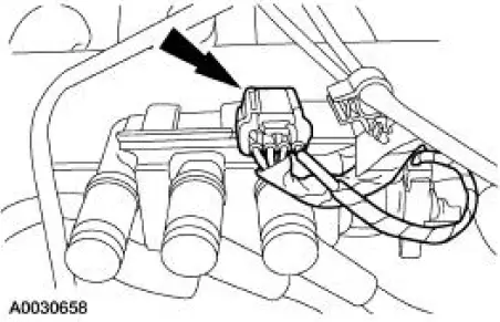
2. Disconnect the ignition coil electrical connector.
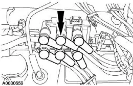
3. CAUTION: Spark plug wires (12286) must be connected to the correct ignition coil terminal. Mark spark plug wire locations before removing them.
Twist while pulling upward to disconnect the spark plug wires.
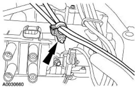
4. Disconnect the accelerator cable retaining clamp from the ignition coil stud bolt.
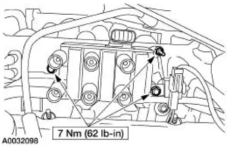
5. Remove the bolts and the ignition coil (12029).
6. NOTE: Apply silicone brake caliper grease and dielectric compound to the inside of the spark plug wire coil boot.
NOTE: Be sure to reinstall the radio ignition interference capacitor (18801) under the correct mounting bolt.
To install, reverse the removal procedure.
 Engine Ignition (Description and Operation)
The ignition coil (12029), which is mounted on the upper intake manifold, can
be described as a coil
pack containing three separate coil units. Each coil unit is individually
controlled by the power ...
 Spark Plug Wire
Special Tool(s)
Remover, Spark Plug Wire
303-106 (T74P-6666A)
Material
Item
Specification
Silicone Brake Caliper Grease
and Dielectric Compound
D7AZ-19A331-A or equiva ...
Other materials:
Lock Cylinder - Door
Removal
1. NOTE: Individual lock cylinders are repaired by discarding the
inoperative cylinder and building
a new lock cylinder using the appropriate lock repair package. The lock
repair package includes
a detailed instruction sheet to build the ne ...
Pinpoint Tests
PINPOINT TEST A: THE ENGINE DOES NOT CRANK AND THE
RELAY DOES CLICK
Test Step
Result / Action to Take
A1 CHECK THE VOLTAGE TO THE STARTER RELAY
YesGO to A2 .
No
REPAIR circuit 1050 (LG/VT) for an open. TEST the
system for normal operation. ...
Anti-Lock Control
Refer to Wiring Diagrams Cell 42 , Anti-Lock Brake for schematic and
connector information.
Special Tool(s)
Worldwide Diagnostic System
(WDS)
418-F224,
New Generation STAR (NGS)
Tester
418-F052, or equivalent scan
tool
73 Digita ...
