Ford Mustang (1999-2004) Service Manual: Register - LH
Removal
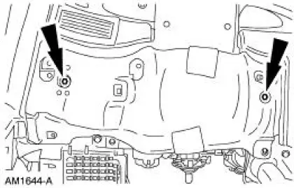
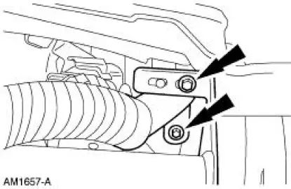
1. Remove the instrument panel steering column cover bolts.
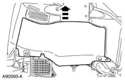
2. Unsnap and remove the instrument panel steering column cover.
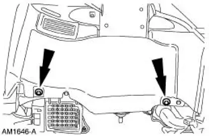
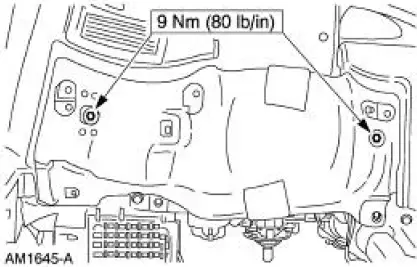
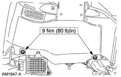
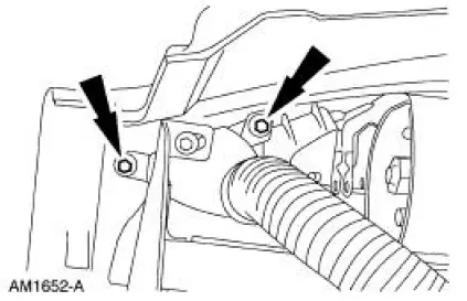
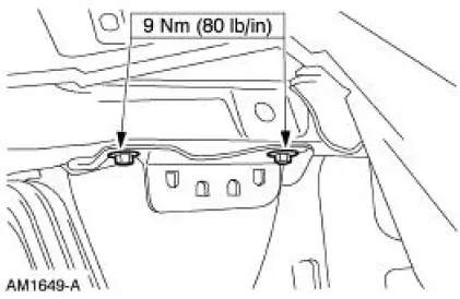
3. Remove the bolts and the steering column reinforcement.
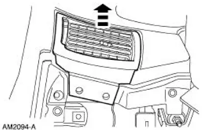
4. Remove the screws.
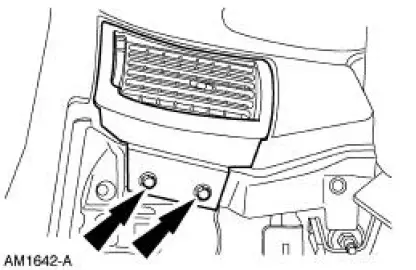
5. Remove the register.
Installation
1. To install, reverse the removal procedure.
Register -Center
Removal and Installation
NOTE: The center register is incorporated into the instrument panel center finish panel.
Nozzle -LH Demister and Hose
Removal
1. Remove the instrument panel. For additional information, refer to Section.
2. Remove the screws.
3. Remove the hose and the nozzle from the instrument panel.
Installation
1. To install, reverse the removal procedure.
Nozzle -RH Demister and Hose
Removal
1. Remove the instrument panel. For additional information, refer to Section.
2. Remove the screws.
3. Remove the hose and the nozzle from the instrument panel.
Installation
1. To install, reverse the removal procedure.
Duct -Floor
Removal
1. Remove the evaporator core housing. For additional information, refer to Section.
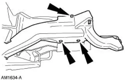
2. Remove the screws and remove the heater outlet floor duct.
Installation
1. To install, reverse the removal procedure.
Duct -Defroster
Removal
1. Remove the instrument panel. For additional information, refer to Section.
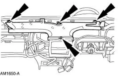
2. Remove the screws and remove the defroster duct.
Installation
1. To install, reverse the removal procedure.
Duct -RH Instrument Panel Register
Removal
1. Remove the instrument panel. For additional information, refer to Section.
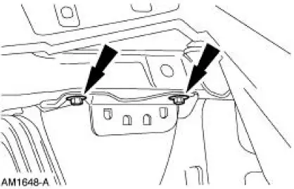
2. Remove the screws and remove the duct.
Installation
1. To install, reverse the removal procedure.
 Air Distribution
NOTE: The air distribution system of this vehicle cannot be equipped
with a cabin air filter.
There are two sources of air available to the air distribution system:
outside air
recirculated air
...
 Plenum Chamber
Removal
1. Remove the instrument panel. For additional information, refer to Section.
2. Remove the audio unit. For additional information, refer to Section.
3. If equipped, remove the CD player. Fo ...
Other materials:
Assembly
1. NOTE: Universal joint kits are to be installed as complete
assemblies only. Do not mix
components from other U-joint kits.
Install the spider.
1. Start a new bearing cup into the driveshaft yoke.
Check the needle bearings for correct positioning.
...
Brake Disc Machining
Special Tool(s)
Gauge, Clutch Housing
308-021 (T75L-4201-A)
Dial Indicator Gauge with
Holding Fixture
100-002 (TOOL-4201-C) or
equivalent
Material
Item
Specification
Metal Surface Cleaner
F4AZ-19A536-RA or equiv ...
Main Control Valve Body
Special Tool(s)
Gauge, Transmission Solenoid
Connectors
307-426
Removal
1. Drain transmission fluid and remove the transmission fluid pan and
filter. For additional
information, refer to Fluid Pan, Gasket and Filter .
2. CAUTION: Do not ...
