Ford Mustang (1999-2004) Service Manual: Removal
Both mounts
1. Disconnect the battery ground cable. For additional information, refer to Section.
2. Remove the coolant bypass tube. For additional information, refer to Section.
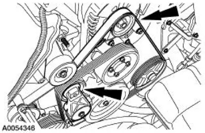
3. Rotate the drive belt tensioner clockwise and detach the drive belt from the generator pulley.
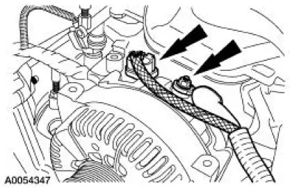
4. Disconnect the generator electrical connections.
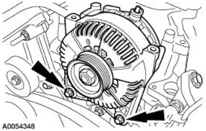
5. Remove the bolts and the generator.
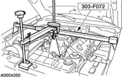
6. Install the special tool.
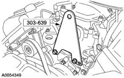
7. Using the special tool, support the engine.
8. Remove the front springs. For additional information, refer to Section.
9. NOTE: RH shown, LH similar.
Remove the six splash-shield pushpins.
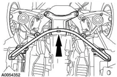
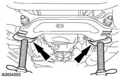
10. Remove the 13 bolts and the cross-brace support.
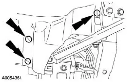
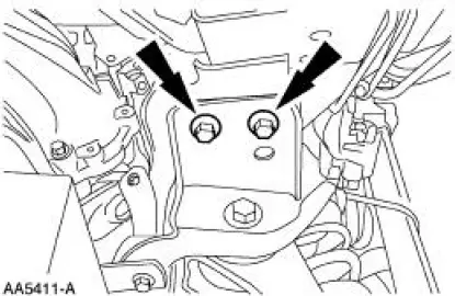
11. NOTE: RH shown, LH similar.
Remove the two engine mount nuts.
12. Using two jackstands, support the subframe.
13. NOTE: Mark the bolts and the crossmember location for assembly reference.
NOTE: RH shown, LH similar.
Remove the four bolts.
14. NOTE: RH shown, LH similar.
Remove the four bolts.
15. Using the jackstands, lower the front subframe.
RH mount
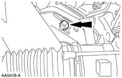
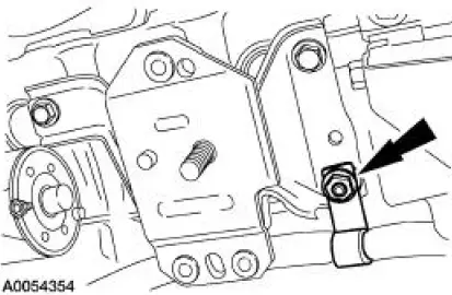
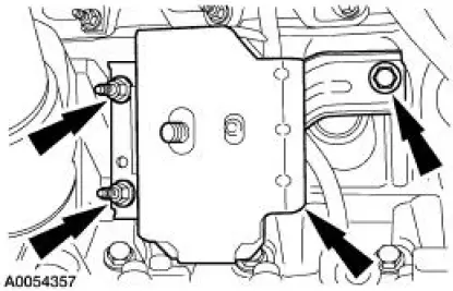
16. Remove the nut and detach the wiring harness.
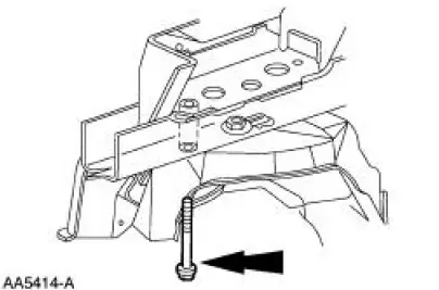
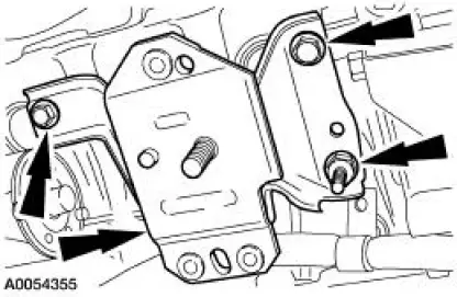
17. Remove the bolts, the studbolt and the engine mount.
LH mount
18. Remove the nuts and detach the ground cables.
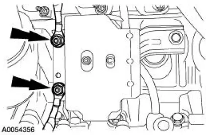
19. Remove the bolt, the studbolts and the engine mount.
 Engine Mount
Special Tool(s)
Support Bracket, Engine
303-639
3-Bar Engine Support Kit
303-F072
Alignment Tool, Subframe
502-004
...
 Installation
LH mount
1. Position the engine mount and install the bolt and studbolts.
2. Attach the ground cables and install the nuts.
RH mount
3. Position the engine mount and install the bolts and studbolt ...
Other materials:
Road Test
NOTE: It may be necessary to have the customer ride along or drive the
vehicle to point out the
concern. During the road test, take into consideration the customer's driving
habits and the driving
conditions. The customer's concern just may be an acceptable ...
Shift Point Road Test
This test verifies that the shift control system is operating
correctly.
1. Bring engine and transmission up to normal operating temperature.
2. Operate vehicle with transmission range selector lever in (D)
position.
3. NOTE: Shift speed ranges a ...
Assembly
1. NOTE: Universal joint kits are to be installed as complete
assemblies only. Do not mix
components from other U-joint kits.
Install the spider.
1. Start a new bearing cup into the driveshaft yoke.
Check the needle bearings for correct positioning.
...
