Ford Mustang (1999-2004) Service Manual: Removal
WARNING: Do not smoke or carry lighted tobacco or open flame of any type when working on or near any fuel related components. Highly flammable mixtures are always present and can ignite. Failure to follow these instructions can result in personal injury.
1. With the vehicle in neutral, position it on a hoist. For additional information, refer to Section.
2. Disconnect the battery ground cable. For additional information, refer to Section.
3. Remove the upper intake manifold. For additional information, refer to Section..
4. Disconnect the following connectors:
- The 42 pin engine bulkhead electrical connector.
- The 16 pin electrical connector.
5. Separate the wiring harness from the dash panel.
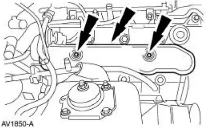
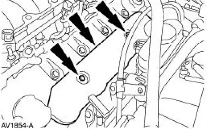
6. Remove the RH ignition coil cover.
- Remove the bolts.
- Remove the coil cover.
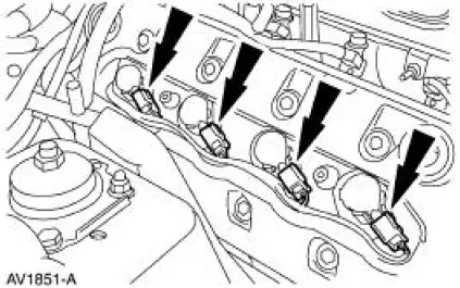
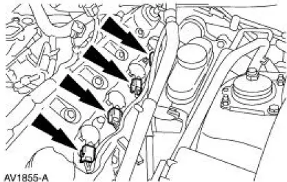
7. Disconnect the RH ignition coil electrical connectors.
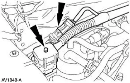
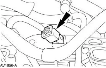
8. Disconnect the heated positive crankcase ventilation (PCV) valve electrical connector.
9. Remove the LH ignition coil cover.
- Remove the bolts.
- Remove the coil cover.
10. Disconnect the LH ignition coil electrical connectors.
11. Disconnect the transmission main control harness electrical connector.
12. Disconnect the engine control jumper harness electrical connector.
13. Remove the wiring harness bracket bolt.
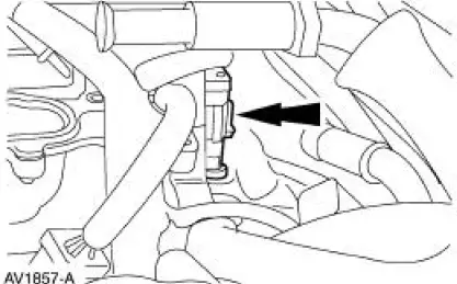
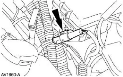
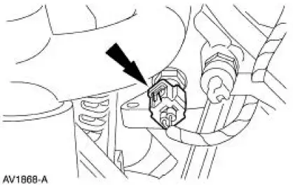
14. Disconnect the RH heated oxygen sensor (HO2S) electrical connector.
15. NOTE: LH side is shown, RH side is similar.
Disconnect the two radio ignition interference capacitor electrical connectors.
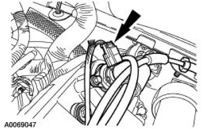
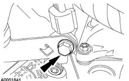
16. Disconnect the battery supply wire from the power distribution box stud.
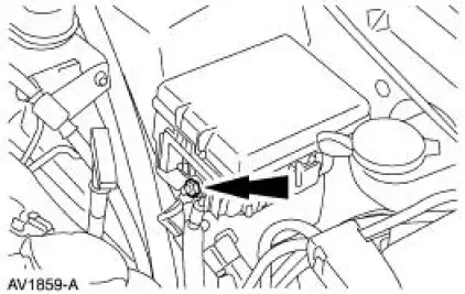
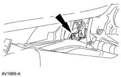
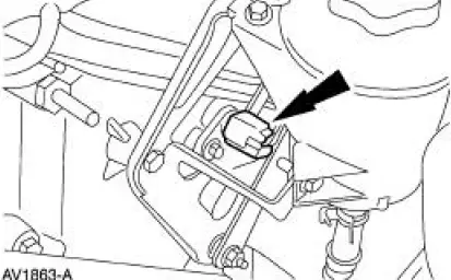
17. NOTE: The electrical connector is located under the power distribution box.
Disconnect the electrical connector.
18. Disconnect the electrical connector.
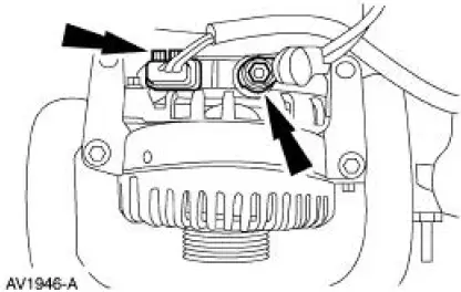
19. Disconnect the following generator electrical connectors:
- Battery power supply wire.
- Voltage regulator.
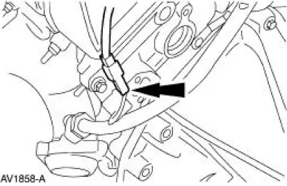
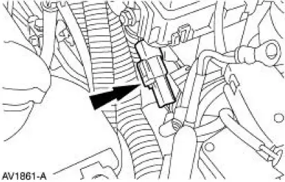
20. Disconnect the camshaft position (CMP) sensor electrical connector.
21. Disconnect the engine coolant temperature (ECT) sensor electrical connector.
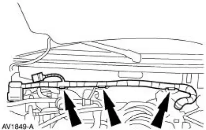
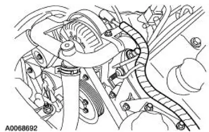
22. Remove the wiring harness.
- Separate the wiring harness from the LH valve cover stud bolt.
- Separate the wiring harness from the power steering reservoir bracket.
 Wiring Harness
...
 Installation
1. Position the wiring harness:
Install the wiring harness retainer onto the LH valve cover stud bolt.
Install the wiring harness retainer into the power steering reservoir.
2. Connect the EC ...
Other materials:
Keyless Entry/Computer Operated Locks
Programming -Keyless Entry Remote Transmitter
NOTE: All keyless entry remote transmitters (15K601) must be
programmed at the same time.
NOTE: All previous transmitter identification codes (TIC's) will be
erased when programming mode is
entered.
...
Installation
1. Install the RH engine insulator.
Install the nuts.
Install the bolts.
2. Install the LH engine insulator.
3. Connect the engine ground strap.
4. Install the bracket.
5. Lower the vehicle.
6. Lower the engine.
7. Raise the vehicle.
8. Ins ...
Axle Assembly
Removal and Installation
1. CAUTION: The vehicle must be on level ground and at curb height.
Mark the rear shock absorbers relative to their protective sleeve.
During installation, raise the suspension to this reference mark before
tightening the
suspens ...
