
Ford Mustang (1999-2004) Service Manual: Universal Joints
The universal joints are:
- lubed-for-life design and require no lubrication.
- equipped with nylon thrust washers, located at each base of the bearing cup, which control end play, position the needle bearing and improve grease movement.
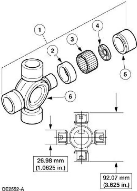
| Item | Part Number | Description |
| 1 | 4635 | Universal joint (U-joint) |
| 2 | - | Grease seal (part of 4635) |
| 3 | - | 32 needle bearings (part of 4635) |
| 4 | - | Thrust washer (part of 4635) |
| 5 | - | Bearing cup (part of 4635) |
| 6 | - | Spider (part of 4635) |
 Driveshaft (Description and Operation)
NOTE: All driveshaft assemblies are balanced. If undercoating the
vehicle, protect the driveshaft to
prevent overspray of any undercoating material.
The driveshaft has the following features ...
 Driveshaft (Removal and Installation)
Material
Item
Specification
Threadlock and
Sealer
E0AZ-19554-AA
WSK-M2G351-A5 (type
II)
Removal and Installation
1. Raise and support the vehicle.
2. Carry out the following:
...
Other materials:
Installation
1. Position the wiring harness:
Install the wiring harness retainer onto the LH valve cover stud bolt.
Install the wiring harness retainer into the power steering reservoir.
2. Connect the ECT sensor electrical connector.
3. Connect the CMP senso ...
Starter Motor - 4.6L
Removal
WARNING: When servicing starter motor (11002) or carrying out other
underhood work in
the vicinity of the starter motor, be aware that the heavy gauge battery
input lead at the starter
solenoid (11390) is "electrically hot" at all times. A prote ...
Air Conditioning (A/C) System Check - Retail Procedure
NOTE: This Retail Procedure is not eligible for claiming on Ford
paid repairs (warranty and ESP).
NOTE: The engine should be run at idle for 10 minutes with the air
conditioning on and set to MAX A/C
before carrying out this retail procedure.
NOTE: Re ...
