Ford Mustang (1999-2004) Service Manual: Camber and Caster Adjustment - Front
All vehicles
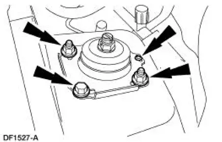
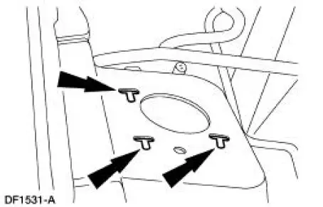
1. Remove the rivet. Loosen the nuts and bolt.
Vehicles requiring camber adjustment
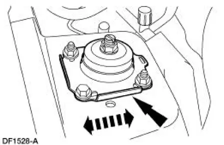
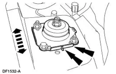
2. Move the front suspension camber adjusting plate (3B391) to the required camber setting.
Vehicles requiring caster adjustment
3. NOTE: If caster adjustment is necessary to resolve a pull, or out of specification cross-caster split, then slotting the shock tower at the front shock absorber (18124) upper mounting point is an acceptable method. This procedure should not be routinely performed with all alignments and only after all other possible sources have been inspected and corrected as necessary.
Determine the amount of caster adjustment needed.
- If no more than 0.6 degree is needed, only one shock tower needs to be slotted.
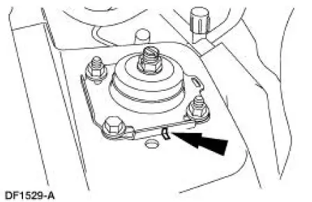
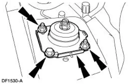
4. Mark the camber position of the front suspension camber adjusting plate (3B391).
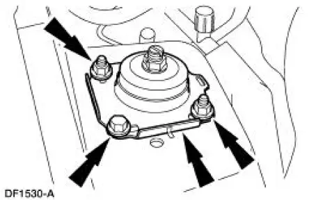
5. Remove the nuts, bolt and the front suspension camber adjusting plate.
6. Raise the front end. Position the strut and spring assembly out of the way. 7. Cut slots perpendicular to the existing camber adjustment slots.
- Moving the top of the front shock absorber toward the rear of the vehicle will increase the caster reading for that side.
- Each millimeter of adjustment should yield approximately 0.12 degree of caster change.
- Do not cut slots any longer than 5 mm (0.2 in.) in any direction.
- Remove any burrs.
- Clean and paint any exposed metal.
8. Position the strut and spring assembly. Lower the front end.
9. Install the front suspension camber adjustment plate, bolt and nuts. Hand tighten the bolt and nuts.
10. Align the camber marks and position the front suspension camber adjustment plate at the correct caster setting.
All vehicles
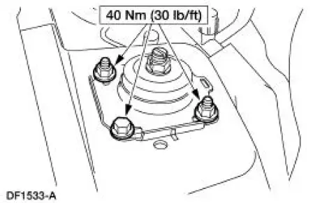
11. Tighten the nuts and bolt.
12. Recheck the wheel alignment. Follow the manufacturer's instructions. Adjust as necessary.
 Component Tests
Ball Joint Inspection
1. Raise and support the vehicle.
2. Prior to performing any inspection of the ball joints, inspect the wheel
bearings.
3. Position a safety stand beneath the front suspension ...
 Camber Adjustment - Rear
1. Loosen the nut.
2. Rotate the bolt and the cam to the correct camber setting.
3. Tighten the nut while holding the bolt and the cam stationary.
4. Recheck the wheel alignment. Follow the manu ...
Other materials:
Installation
CAUTION: Electronic modules are sensitive to static electrical
charges. If exposed to
these charges, damage may result.
1. NOTE: Two technicians are necessary to carry out this step.
Install the instrument panel.
2. Install the upper instrument pa ...
Front Subframe - 4.6L (4V) Engine
Special Tool(s)
3-Bar Engine Support Kit
303-F072
Lifting Bracket, Engine
303-D088 (D93P-6001-A2)
Removal and Installation
All vehicles
1. Remove the steering gear. For additional information, refer to Section .
2. Remove the low ...
Master Cylinder
Removal
1. Disconnect the fluid level sensor connector.
2. Disconnect the brake tubes.
3. Remove the brake master cylinder nuts.
4. Remove the brake master cylinder (2140).
Installation
1. To install, reverse the removal procedure.
Bleed the brake ...
