Ford Mustang (1999-2004) Service Manual: Evaporative Emission Test Port
Removal and Installation
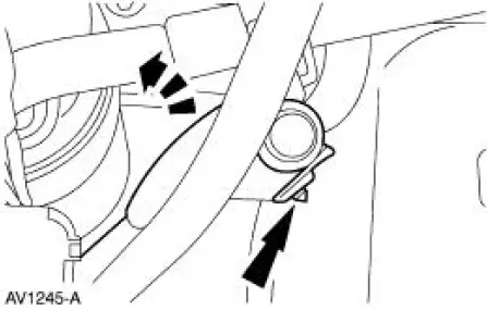
1. Disconnect the pin-type retainer.
2. Raise and support the vehicle. For additional information, refer to Section.
3. Remove the RH front wheel. For additional information, refer to Section.
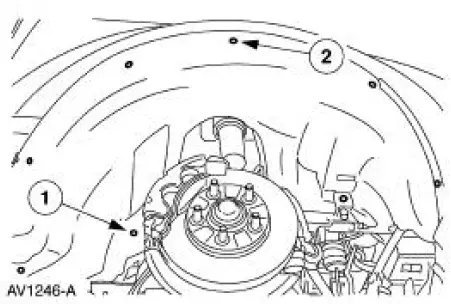
4. Remove the RH front splash shield.
1. Remove the three screws.
2. Remove the five pin-type retainers.
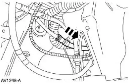
5. Remove the evaporative emission test port by disconnecting at the EVAP canister purge outlet tube junction.
6. To install, reverse the removal procedure.
- Leak test the system. For additional information, refer to Evaporative Emission System Leak Test in this section.
- Carry out the evaporative emission repair verification drive cycle. For additional information, refer to Evaporative Emission Repair Verification Drive Cycle in this section.
Evaporative Emission Canister Vent Solenoid
Removal and Installation
1. Remove the canister vent solenoid. For additional information, refer to Evaporative Emission Canister in this section.
 Fuel Vapor Control Tube Assembly Valve
Removal and Installation
1. Remove the fuel tank. For additional information, refer to
Section.
2. Remove the retainers.
3. NOTE: The fuel vapor vent valve, fuel vapor control valve and the ...
 Electronic Engine Controls
General Specifications
Torque Specifications
...
Other materials:
Engine (Installation)
Special Tool(s)
Spreader Bar
303-D089 (D93P-6001-A3)
Support Bracket, Engine
303-639
Lifting Bracket, Engine
303-D087 (D93P-6001-A1)
Lifting Bracket, Engine
303-D088 (D93P-6001-A2)
Lifting Brac ...
Recreational towing
Note: Do not tow with the Shelby GT500 model. It cannot tow a trailer.
Note: Do not exceed the trailer weight for your vehicle configuration
listed in the chart below.
Note: Make sure to take into consideration trailer frontal area. Do not
exceed 12 feet2 (1 ...
Lumbar Assembly
Removal and Installation
All vehicles
1. Remove the front seat. For additional information, refer to Seat-Front
Power in this section.
2. Release the J-clip.
3. Remove the seat backrest latch handle knob (62762).
4. Pull the seat backrest trim cover ...
