Ford Mustang (1999-2004) Service Manual: Turn Signal and Hazard Lamps
Refer to Wiring Diagrams Cell 90 , Turn/Stop/Hazard Lamps for schematic and connector information.
Special Tool(s)
 |
73 III Automotive Meter 105-R0057 or equivalent |
Inspection and Verification
1. Verify the customer concern.
2. Visually inspect for the following obvious signs of mechanical and electrical damage.
Visual Inspection Chart
| Mechanical |
Electrical |
|
|
3. If an obvious cause for an observed or reported concern is found, correct the cause (if possible) before proceeding to the next step.
4. If the cause is not visually evident, verify the symptom and refer to the Symptom Chart.
Symptom Chart
| Condition | Possible Sources | Action |
|
|
|
|
|
|
|
|
|
|
|
|
|
|
|
Pinpoint Tests
PINPOINT TEST J: THE TURN SIGNAL LAMPS ARE NEVER ON
| Test Step | Result / Action to Take |
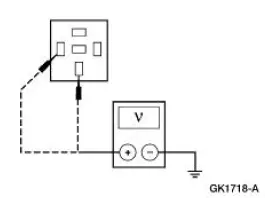
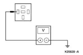
| J1 CHECK THE VOLTAGE TO THE ELECTRONIC FLASHER | Yes GO to J2 . No REPAIR the circuit in question. TEST the system for normal operation. |
|
|
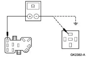
| J2 CHECK CIRCUIT 44 (LB) | Yes GO to J3 . No REPAIR the circuit. TEST the system for normal operation. |
|
|
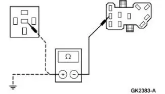
| J3 CHECK THE CONTINUITY OF THE MULTIFUNCTION SWITCH | Yes INSTALL a new electronic flasher. TEST the system for normal operation. No INSTALL a new multifunction switch. REFER to Section. TEST the system for normal operation. |
|
PINPOINT TEST K: THE HAZARD FLASHER LAMPS ARE NEVER ON
| Test Step | Result / Action to Take |
| K1 CHECK THE VOLTAGE TO THE ELECTRONIC FLASHER | Yes GO to K2 . No REPAIR the circuit. TEST the system for normal operation. |
|
|
| K2 CHECK CIRCUIT 385 (WH/RD) | Yes GO to K3 . No REPAIR the circuit. TEST the system for normal operation. |
|
|
| K3 CHECK THE CONTINUITY OF THE MULTIFUNCTION SWITCH | Yes INSTALL a new electronic flasher. TEST the system for normal operation. No INSTALL a new multifunction switch; REFER to Section. TEST the system for normal operation. |
|
 Stoplamps
Refer to Wiring Diagrams Cell 90 , Turn/Stop/Hazard Lamps for
schematic and connector information.
Special Tool(s)
73III Automotive Meter or
equivalent
105-R0057
Inspection and Ve ...
 Parking, Rear and License Lamps
Refer to Wiring Diagrams Cell 92 , Exterior for schematic and connector
information.
Special Tool(s)
73 III Automotive Meter or
equivalent
105-R0057
Inspection and Verification
1 ...
Other materials:
Support Straps
Removal
WARNING: Do not smoke, carry lighted tobacco or an open flame of any
type when
working on or near any fuel-related components. Highly flammable mixtures are
always present
and may be ignited, possibly resulting in personal injury.
WARNING: Fuel suppl ...
Cleaning the interior
WARNING: Do not use cleaning solvents, bleach or dye on the
vehicle’s safety belts, as these actions may weaken the belt
webbing.
WARNING: On vehicles equipped with seat-mounted airbags, do
not use chemical solvents or strong detergents. Such products
could ...
System menu features
Your system offers many menu features, such as allowing you to adjust
the touchscreen brightness, time and language, feedback and system
settings. You can access these options by pressing the MENU hard
button.
...
