Ford Mustang (1999-2004) Service Manual: Synchronizers
Disassembly
NOTE: This procedure applies to all synchronizer assemblies (7124). The synchronizers are slightly different in design. Notation is made where procedural differences occur.
1. On the third/fourth speed synchronizer and the fifth speed synchronizer, scribe an alignment mark on the sliding sleeve and the hub for assembly reference.
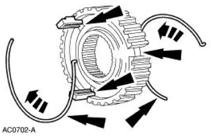
2. NOTE: Only the synchronizer hub insert springs (7109) and the synchronizer hub inserts (7A044) are available separately.
Remove the synchronizer hub inserts and the hub insert springs.
3. The first/second speed synchronizer sliding sleeve, the hub, and the output shaft are an assembly. Do not attempt to separate the hub from the output shaft. Discard the entire assembly if wear or damage to the synchronizer or output shaft is evident.
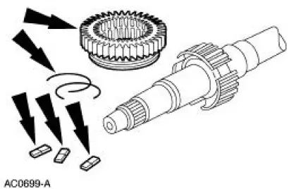
4. On the third/fourth speed synchronizer and the fifth speed synchronizer, remove the sliding sleeve.
Assembly
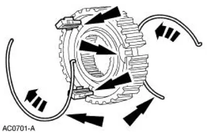
1. NOTE: Both synchronizer hub insert springs engage the same synchronizer hub insert but rotate in the opposite direction.
NOTE: The third/fourth speed synchronizer uses the winged synchronizer hub inserts.
Install the synchronizer hub inserts and the hub insert springs. Verify that the spring tabs are positioned over the hub inserts.

2. CAUTION: Match the alignment marks made during disassembly. The sleeve and the hub have an extremely close fit. Hold the sleeve and hub square to prevent jamming.
Do not force the sleeve onto the hub.
On the third/fourth speed synchronizer and the fifth speed synchronizer, install the sliding sleeve.
 Countershaft Bearing
Special Tool(s)
Bearing Replacer
308-061 (T77J-7025-L)
Front Bearing Replacer
308-062 (T77J-7025-M)
Mainshaft Front Bearing
Replacer
308-081 (T82T-7003-DH)
...
 Transmission (Assembly)
Special Tool(s)
Dial Indicator with Bracketry
100-002 (TOOL-4201-C) or
Equivalent
Gauge, Clutch Housing
308-021 (T75L-4201-A)
Extension Housing Seal
Replacer ...
Other materials:
Installation
1. CAUTION: Lubricate the filler pipe check valve area and the
tank-to-filler pipe
grommet with Serfactant prior to assembly or damage to the filler pipe check
valve will
occur.
NOTE: A new grommet must be used for the installation procedure due to
its dest ...
Entertainment System - General Information
Audio System (Diagnosis and Testing)
Refer to Wiring Diagrams Cell 130 , Radio for schematic and connector
information.
Special Tool(s)
73III Automotive Meter
105-R0057 or equivalent
Inspection and Verification
1. Verify the customer con ...
Moulding - Roof Side
Removal and Installation
1. Remove the weatherstrip.
2. Remove the exterior roof side moulding screws.
3. Remove the interior roof side moulding screws.
4. Remove the roof side moulding screw.
5. Release the clips.
1. Lift up to release the two ...
