Ford Mustang (1999-2004) Service Manual: Toe Adjustment - Front
1. Start the engine and center the steering wheel.
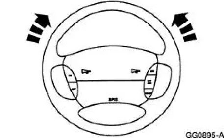
2. Turn the engine off, and hold the steering wheel in the straight forward position by attaching a rigid link from the steering wheel to the seat.
3. Check the toe settings. Follow the manufacturer's instructions.
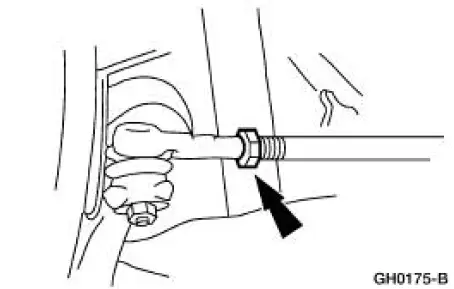
4. Remove the clamps.

5. Loosen the nuts.
- Clean and lubricate the nut(s) and front wheel spindle tie-rod threads.
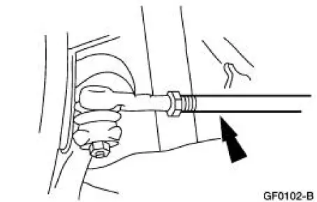
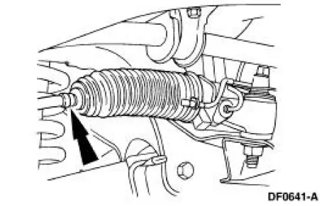
6. NOTE: Do not allow the steering gear bellows to twist when the front wheel spindle tie-rod (3280) is rotated.
Rotate the front wheel spindle tie-rods.
7. Tighten the nuts.
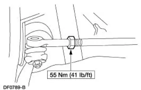
8. Install the clamps.
9. Recheck the toe settings. Follow the manufacturer's instructions.
 Camber Adjustment - Rear
1. Loosen the nut.
2. Rotate the bolt and the cam to the correct camber setting.
3. Tighten the nut while holding the bolt and the cam stationary.
4. Recheck the wheel alignment. Follow the manu ...
 Toe Adjustment - Rear
1. Loosen the nuts.
To prevent damage to the ball joints, hold the tie-rod ends while
loosening the nuts.
2. Rotate the toe link to the correct toe setting.
3. Tighten the nuts.
To ...
Other materials:
Oil Pan
Special Tool(s)
3 Bar Engine Support Kit
303-F072
Lifting Bracket Set, Engine
303-D095 (D94L-6001-A) or
equivalent
Material
...
Compressor to Condenser Discharge Line - 4.6L
Material
Item
Specification
PAG Refrigerant Compressor
Oil (R-134a Systems)
F7AZ-19589-DA (Motorcraft YN-
12-C)
WSH-M1C231-
B
Removal and Installation
NOTE: Installation of a new suction accumulator is not required when
repairing the ...
Generator - 4.6L 2V
Removal and Installation
1. Disconnect the battery (10655). For additional information, refer
to Section.
2. Relieve the accessory drive belt (8620) tension and remove the belt
from the generator pulley.
Leave the belt in place for reinstallation ...
