Ford Mustang (1999-2004) Service Manual: Material
| Item | Specification |
| Threadlock and Sealer E0AZ-19554-AA | WSK-M2G351-A5 (type II) |
| Shoulder Bolt Kit F5ZZ-76539A04-A | - |
NOTE: Before starting the adjustment process, inspect the top for damage, make sure that the door window glass and rear quarter glass are correctly adjusted then completely lower all window glass.
NOTE: After each adjustment make sure the convertible top operates correctly.
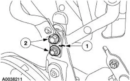
The Convertible Top Dowel Pins Fall Forward (Overshoot) or Rearward (Undershoot). The Receiver Cups - Cam Bolt Adjustment.
1. Remove the quarter trim panel. For additional information, refer to Section.
2. Close the convertible top and examine the position of the dowel pins relative to the receiver cups.
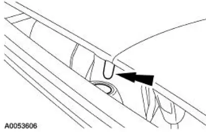
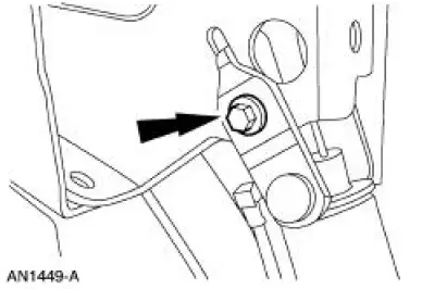
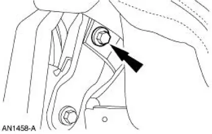
3. Move the convertible top to the half-open position to access the cam bolt.
4. NOTE: Rotating the top of the cam bolt toward the front of the vehicle will lengthen the top, increase the tension on the top and increase pull-down effort. Rotating the cam bolt in the opposite direction will have the opposite effect.
NOTE: Turn the adjusting cam one notch at a time.
Adjust the adjusting cam as needed.
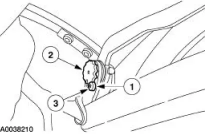
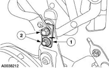
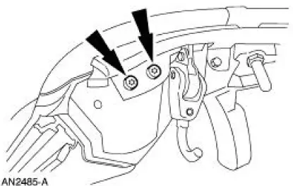
1. Remove the cam stop set screw.
2. Rotate the adjusting cam.
3. Install the cam stop set screw.
5. Make sure the convertible top operate correctly.
6. Install the quarter trim panel. For additional information, refer to Section.
7. Close the convertible top.
Convertible Top Lifts Up Unevenly - Lift Cylinder and C-pivot Inspection
8. Remove the quarter trim panel. For additional information, refer to Section.
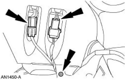
9. NOTE: This step applies to vehicles equipped with the Mach sound system.
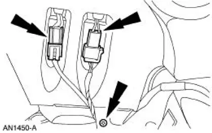
Remove the screws and disconnect the electrical connectors.
10. Remove the screws.
11. Remove the speakers. For additional information, refer to Section.
12. Move the convertible top to the half-open position and support the convertible top in that position.
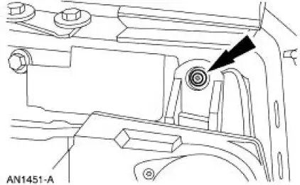
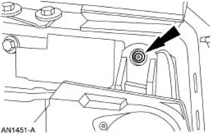
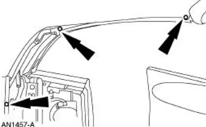
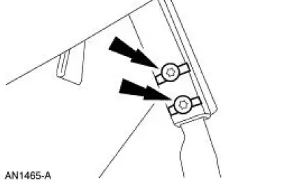
13. Remove the lift cylinder rod mounting bolts.
14. Remove the nuts and support the lift cylinders.
15. Using the convertible top switch, retract the lift cylinder rods and check for bent or binding rods.
If one rod bottoms out 25mm (1 inch) or more before the other, the lagging lift cylinder may be bent and will need to be replaced.
16. With the lift cylinder rods retracted, manually lower the convertible top.
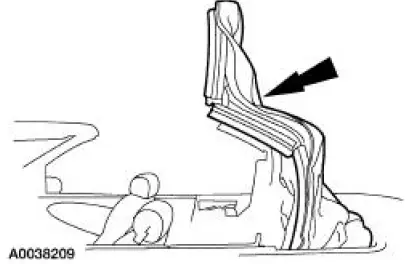
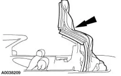
17. Manually lift each side rail 7.5-10 cm (3-4 inches) to check for obvious binding. Side arms should have equal resistance, side-to-side. If the resistance is noted, loosen the clamp load of the c-pivot rivet with using a center pinch. If a dramatic resistance is still noted replace the cpivot rivet with shoulder bolt kit (F5ZZ-76539A04-A).
18. Position the lift cylinders and install the nuts.
19. Install the two cylinder rod mounting bolts.
20. Install the speakers. For additional information, refer to Section.
21. Install the screws.
NOTE: This step applies to vehicles equipped with the Mach sound system.
22. Install the screws and connect the electrical connectors.
23. Install the quarter trim panel. For additional information, refer to Section .
24. Make sure the convertible top operate correctly.
25. Close the convertible top.
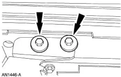
Convertible Top No. 1 Bow is Not Flush to the Header - Balance Link Adjustment
CAUTION: Over adjustment of the balance link can cause the convertible top to bind up in the convertible top well.
CAUTION: If the balance link is raised the B-hinge must be adjusted to keep the door window glass from striking the convertible top, preventing the door from closing.
26. Remove the quarter trim panel. For additional information, refer to Section.
NOTE: Lowering the balance link will raise the No. 1 bow position to the vehicle header and increase the pull down effort. Raising the balance link will lower the No. 1 bow to the header of the vehicle and decrease the pull-down effort.
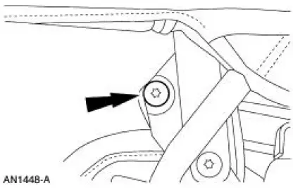
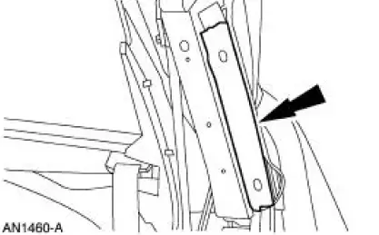
27. Adjust the balance link assembly.
1. Scribe a mark on the balance link.
2. Loosen the bolts.
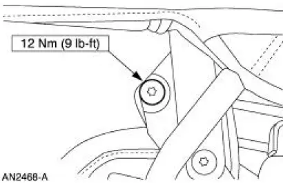
28. Tighten the balance link assembly.
1. Move the balance link assembly.
2. Tighten the bolts.
29. Make sure the convertible top operates correctly.
30. Install the quarter trim panel. For additional information, refer to Section.
31. Close the convertible top.
Convertible Top Appears Low at the Center of the Door Window Glass - B-hinge Adjustment
32. Remove the quarter trim panel. For additional information, refer to Section.
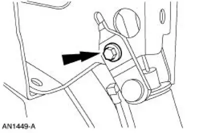
NOTE: If the B-hinge set screw is adjusted to raise or lower the B-hinge, inspect the header height, top pull down and dowl and receiver clearance. Adjust the cam bolt and balance link as necessary.
33. Tighten the lock nut.
- Use Threadlock and sealer on the lock nut.
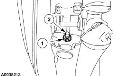
34. Tighten the lock nut.
- Threadlock and sealer on the lock nut.
35. Make sure the convertible top operate correctly.
36. Install the quarter trim panel. For additional information, refer to Section.
37. Close the convertible top.
Convertible Top Assembly - Side Rail, Folding Top
1. Remove the side quarter trim panel. For additional information, refer to Section.
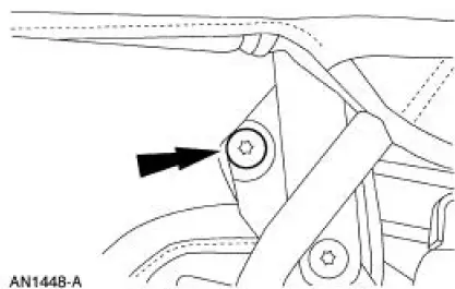
2. If necessary, remove the bolts.
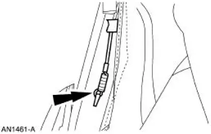
3. Remove the nut and bolts and position the front safety belt retractor aside.
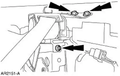
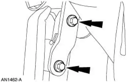
4. Remove the two cylinder rod mounting bolts.
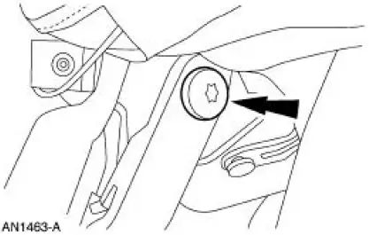
5. Remove the cylinder rod mounting nut.

6. Remove the screw and disconnect the two electrical connectors.
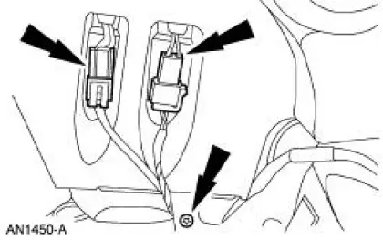
7. Remove the screw.
8. Remove the speaker.
9. Remove the screws and the front seal.
10. Remove the rail seals.
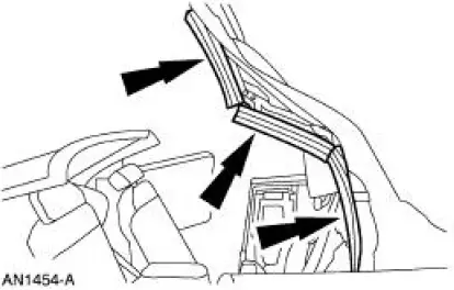
11. Remove the rail seal retainers.
12. Remove the headliner pin-type retainers.
13. Remove the headliner screws.
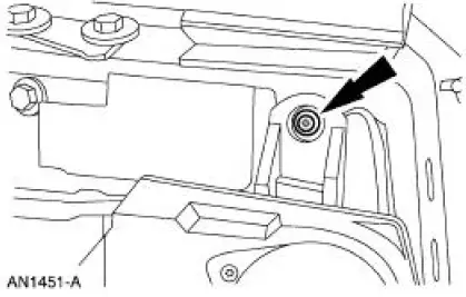
14. Remove the speed nut.
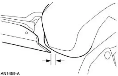
15. Measure the gap between the front of the side rail and the header. Record the figure and the position of the folding top.
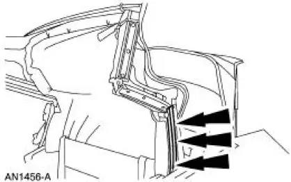
16. Separate the vinyl top cover flap from the rear rail.
17. Disconnect the side tension cable from the rear rail.
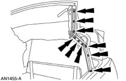
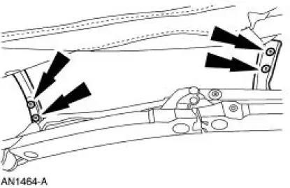
18. Remove the two bolts.
19. Loosen the bolt, but do not remove it.
20. NOTE: Do not latch the folding top after re-positioning.
Position the folding top in the full up position.
21. Disconnect the number two and number three bows from the side rail assembly.
22. NOTE: Mark the centerline locations for the number four bow screws.
Remove the screws.
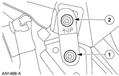
23. Disconnect the mounting bracket.
1. Loosen the bottom bolt.
2. Remove the upper bolt.
24. Remove the side rail.
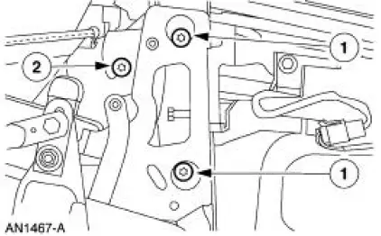
1. Remove the two bolts.
2. Loosen the bolt.

 Installation
1. Position the side rail and install the bolts.
2. NOTE: Tighten the bottom bolt first.
Connect the mounting bracket and install the bolts.
3. NOTE: Line up the marks in the number four bow.
Ti ...
Other materials:
Brake Caliper Support Bracket
Removal
1. Raise and support the vehicle.
2. Remove the tire and wheel assembly.
3. CAUTION: Do not allow the rear disc brake caliper (2552) to
hang from the rear
wheel brake hose (2A442)
Remove the rear disc brake caliper bolts and position the ...
Sprockets
1. WARNING: To avoid the possibility of personal injury or damage
to the vehicle, do
not operate the engine with the hood open until the fan blade has been
examined for
possible cracks and separation.
NOTE: Specifications show the expected minimum or ma ...
Anti-Theft - Passive Anti-Theft System (PATS) (Diagnosis and Testing)
Refer to Wiring Diagrams Cell 112 , Anti-Theft for schematic and connector
information.
Refer to Wiring Diagrams Cell 60 , Instrument Cluster for schematic and
connector information.
Special Tool(s)
73III Automotive Meter
105-R0057 or equivalen ...
