Ford Mustang (1999-2004) Service Manual: Valve Seals
Special Tool(s)
 |
Valve Spring Compressor 303-452 (T93P-6565-AR) |
 |
Valve Stem Seal Replacer 303-383 (T91P-6571-A) |
 |
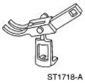
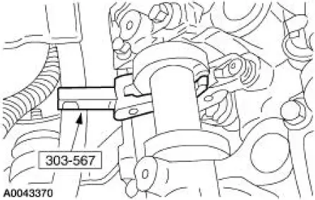
Compressor, Valve Spring (Exhaust) 303-567 (T97P- 6565-AH) |
Material
| Item | Specification |
| Super Premium SAE 5W-20 Motor Oil XO-5W20-QSP | WSS-M2C153- H |
Removal and Installation
1. Remove the roller followers. For additional information, refer to Camshaft Roller Follower in this section.
2. Remove the spark plug (12405) from the applicable cylinder.
3. Position the piston (6102) of the cylinder being serviced at the bottom of the stroke.
4. CAUTION: If air pressure has forced the piston to the bottom of the cylinder, any loss of air pressure will allow the valve to fall into the cylinder. If air pressure must be removed, support the valve prior to removal.
Use compressed air in the cylinder to hold both valves in position.
5. Using the special tool, compress the valve spring (6513).
6. NOTE: Valve stem seals should be visually inspected if not installing new seals.
Remove the valve stem seals.
1. Remove the valve spring retainer keys.
2. Remove the valve spring retainers.
3. Remove the valve springs.
4. Remove the valve stem seals.
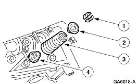
7. NOTE: Lubricate the lip of the new seal with clean engine oil prior to installation.
To install, reverse the removal procedure.
 Installation
1. CAUTION: The timing chain procedures must be followed exactly or
damage to the
valve and pistons will result.
Compress the tensioner plunger, using an edge of a vise.
2. While holding the ratch ...
 Hydraulic Lash Adjuster
Removal and Installation
1. Remove the roller followers. For additional information, refer to Camshaft
Roller Follower in this
section.
2. Remove the eight hydraulic lash adjusters.
3. Inspect the ...
Other materials:
Cleaning the exterior
Wash your vehicle regularly with cool or lukewarm water and a neutral
pH shampoo, such as Motorcraft® Detail Wash.
• Do not use a commercial or high-pressure wand on the surface or
edge of stripes and graphics. This can cause damage to the film and
cause th ...
Exhaust Manifold LH
Removal and Installation
1. Position the steering wheel straight ahead and lock the column.
2. Disconnect the battery ground cable. For additional information, refer to
Section.
3. Raise the vehicle. For additional information, refer to Section.
4. Remove ...
Power seats
WARNING: Never adjust the driver’s seat or seat back when the
vehicle is moving.
WARNING: Before returning the seat back to its original
position, make sure that cargo or any objects are not trapped
behind the seat back.
The power seat control is located
on ...
