Ford Mustang (1999-2004) Service Manual: Valve Stem to Valve Guide Clearance
Special Tool(s)
| Dial Indicator Gauge with Holding Fixture 100-002 (TOOL-4201-C) or equivalent | |
| Clearance Gauge, Valve Guide 303-004 (TOOL-6505-E) or equivalent |
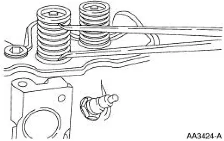
NOTE: Valve stem diameter must be within specifications before checking valve stem to valve guide clearance.
1. NOTE: If necessary, use a magnetic base.
Install a Valve Guide Clearance Gauge on the valve stem and install a Dial Indicator Gauge with Holding Fixture. Lower the valve until the Valve Guide Clearance Gauge contacts the upper surface of the valve guide.
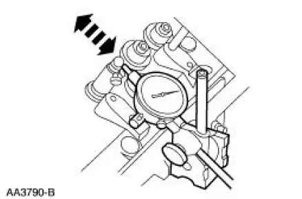
2. Move the Valve Guide Clearance Gauge toward the indicator and zero the indicator. Move the Valve Guide Clearance Gauge away from the indicator and note the reading. The reading will be DOUBLE the valve stem-to-valve guide clearance. Valves with oversize stems will need to be installed if out of specification.
Valve -Inspection
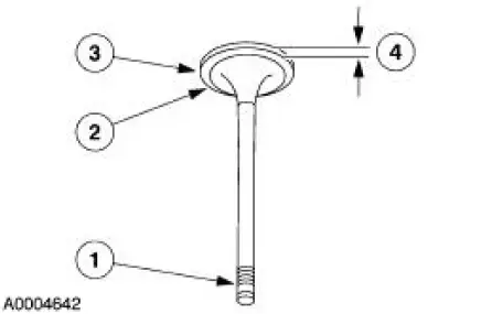
1. Inspect the following valve areas:
1. the end of the stem for grooves or scoring 2. the valve face and the edge for pits, grooves or scores 3. the valve head for signs of burning, erosion, warpage and cracking 4. the valve margin for wear
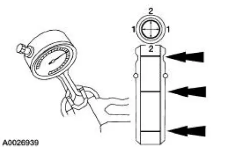
Valve -Guide Inner Diameter
1. Measure the inner diameter of the valve guides in two directions where indicated.
- Refer to the appropriate section in Group 303 for the procedure.
2. If the valve guide is not within specifications, ream the valve guide and install a valve with an oversize stem or remove the valve guide and install a new valve guide.
Valve -Guide Reaming
1. Use a hand-reaming kit to ream the valve guide.
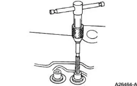
2. Reface the valve seat.
3. Clean the sharp edges left by reaming.
Valve -Spring Installed Length
1. Measure the installed length of each valve spring.
- Refer to the appropriate section in Group 303 for the procedure.
- If out of specification, install new components. Refer to the appropriate section in Group 303 for the procedure.
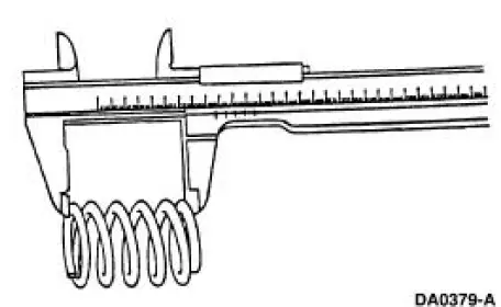
Valve -Spring Free Length
1. Measure the free length of each valve spring.
- Refer to the appropriate section in Group 303 for the procedure.
- If out of specification, install new components as necessary. Refer to the appropriate section in Group 303 for the procedure.
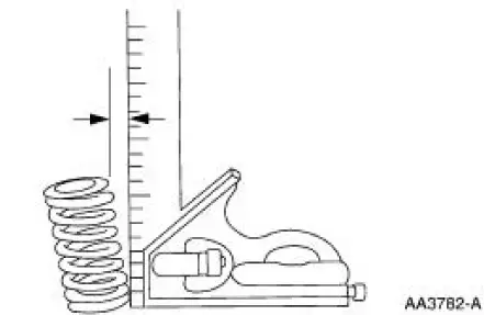
Valve -Spring Squareness
1. Measure the out-of-square on each valve spring.
- Turn the valve spring and observe the space between the top of the valve spring and the square. Install a new valve spring if out of square. Refer to the appropriate section in Group 303 for the procedure.
 Connecting Rod - Side Clearance
1. Measure the clearance between the connecting rod and the crankshaft.
Verify the measurement
is within specification.
Refer to the appropriate section in Group for the procedure.
If out of ...
 Valve Spring Strength
Special Tool(s)
Pressure Gauge, Valve/Clutch
Spring
303-006 (TOOL-6513-DD) or
equivalent
1. Use a Valve/Clutch Spring Pressure Gauge to check the valve spring for
correct strength ...
Other materials:
Battery and Cables
Vehicles are equipped with a 12 volt maintenance-free battery that
contains a built-in hydrometer. The
hydrometer eye indication is as follows:
A green dot means the battery is OK.
A yellow dot, red dot, or when the green dot is not visible,
...
Input Shaft and Bearing
Special Tool(s)
Remover, Driver Pinion
Bearing Cone
205-D002 (D79L-4621-A) or
equivalent
Installer, Drive Pinion Bearing
Cone
205-011 (T57L-4621-B)
Remover/Installer, Bearing
Tube
308-024 (T75L-7025-B)
Disas ...
Synchronizers
Disassembly and Assembly
NOTE: This procedure applies to all synchronizer assemblies.
1. Scribe an alignment mark on the sliding sleeve and the hub for assembly
reference.
2. Remove the sliding sleeve, then remove the synchronizer struts and the
springs.
3 ...
