Ford Mustang (1999-2004) Service Manual: Input Shaft and Bearing
Special Tool(s)
 |
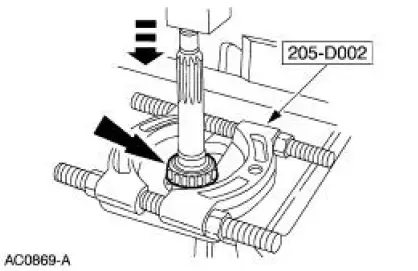
Remover, Driver Pinion Bearing Cone 205-D002 (D79L-4621-A) or equivalent |
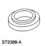 |
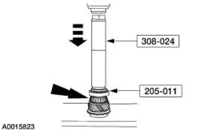
Installer, Drive Pinion Bearing Cone 205-011 (T57L-4621-B) |
 |
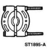
Remover/Installer, Bearing Tube 308-024 (T75L-7025-B) |
Disassembly and Assembly
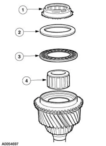
1. Disassemble the input shaft.
1. Remove the third/fourth synchronizer blocking ring.
2. Remove the input shaft thrust washer.
3. Remove the input shaft thrust bearing.
4. Remove the input shaft pocket bearing.
- Inspect all components for wear or damage. Install new components as necessary.
2. Using the special tool and a press, remove the input shaft front bearing assembly. Discard the bearing.
3. Inspect the input shaft and bearings for wear or damage. Install new components as necessary.
4. Using the special tools and a press, install the new input shaft front bearing.
5. Install the input shaft pocket bearing, the washer, input shaft bearing and the third/fourth synchronizer blocking ring.
- Lubricate the bearing and bearing race with petroleum jelly.
 Transmission (Disassembly)
Special Tool(s)
Remover, Mainshaft Bearing
308-058 (T77J-7025-H)
Screw, Bearing Removal tube
308-092 (T84T-7025-B)
Holding Fixture, Transmission
307-003 (T57L- ...
 Output Shaft
Special Tool(s)
Remover, Drive Pinion Bearing
Cone
205-D002 (D79L-4621-A) or
equivalent
Installer, Drive Pinion Bearing
Cone
205-011 (T57L-4621-B)
...
Other materials:
Cable Adjustment
1. NOTE: Make sure that the range selector lever is tight
against the rearward overdrive stop.
Place the transmission range selector lever in the overdrive
position.
2. Raise and support the vehicle. For additional information, refer
to Section.
...
Front Bumper
Special Tool(s)
Heavy-Duty Riveter
501-D011 (D80L-23200-A)
Removal and Installation
All vehicles except Cobra
1. Remove the front bumper cover. For additional information, refer to Front
Bumper Cover in this
section.
Cobra
2. Remove the charge ...
Inspection and Verification
NOTE: A new instrument cluster must be reconfigured.
NOTE: The instrument panel dimmer switch is a part of the headlamp
switch.
1. Verify the customer concern.
2. Visually inspect for obvious signs of electrical damage.
Visual Inspection Chart
Electric ...
