
Ford Mustang (1999-2004) Service Manual: Actuator - Speed Control Servo
1. CAUTION: Electronic modules are sensitive to static electrical charges. If exposed to these charges, damage may result.
Disconnect the battery ground cable.
2. Remove the LH wheel and tire; refer to Section.
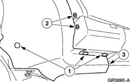
3. Position aside the LH front splash shield.
1. Remove the pin-type retainers.
2. Remove the screws.
3. Position aside the LH front splash shield.
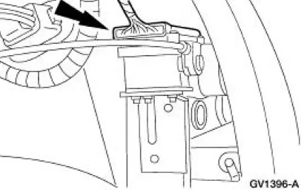
4. Disconnect the speed control servo electrical connector.
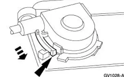
5. Depress the locking tab and rotate the speed control actuator cable cap to remove.
6. Disconnect the speed control cable from the throttle nailhead.
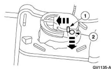
7. Disconnect the speed control actuator cable from the speed control servo pulley.
1. Gently push in the retaining spring.
2. Disconnect the speed control cable slug from the speed control servo pulley.
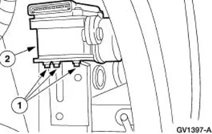
8. Remove the speed control servo.
1. Remove the bolts.
2. Remove the speed control servo.
Installation
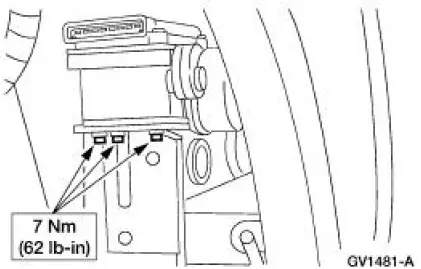
1. NOTE: When the battery is disconnected and reconnected, some abnormal drive symptoms may occur while the vehicle relearns its adaptive strategy. The vehicle may need to be driven 16 km (10 mi) or more to relearn the strategy.
To install, reverse the removal procedure.
 Actuator Cable - Speed Control-Cobra
1. Remove the speed control actuator cable end from the throttle body.
1. Lift the speed control cable from the throttle nailhead.
2. Release the speed control cable from the throttle bracket.
...
 Switch - Deactivator
Removal
1. Disconnect the battery ground cable.
2. Remove the deactivator switch.
1. Disconnect the deactivator switch electrical connector.
2. Detach the lower deactivator switch hook.
3 ...
Other materials:
Fuel quality
Note: Use of any fuel other than those recommended may cause
powertrain damage and a loss of vehicle performance; repairs may not be
covered under warranty.
Choosing the Right Fuel
Use only unleaded fuel or unleaded fuel blended with a maximum of
15% ethanol. ...
Window Glass - Quarter
Removal
1. Remove the quarter trim panel. For additional information, refer
to Section.
2. Remove the roof side trim moulding. For additional information, refer
to Section.
3. Remove the exterior quarter glass weatherstrip.
4. Remove the nuts.
...
Parking Brake (Description and Operation)
The parking brake system is cable-actuated and controlled by an independent
hand-operated parking
brake control (2780). To apply parking brake, pull parking brake control upward
as far as possible.
The parking brake system is an AUTO-ADJUST system ...
