Ford Mustang (1999-2004) Service Manual: Reverse Servo Assembly
Special Tool(s)
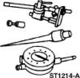 |
Dial Indicator Gauge with Holding Fixture 100-002 (TOOL-4201-C) |
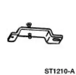 |
Remover/Installer, Servo Piston 307-251 (T92P-70023-A) |
 |
Installer, Servo Piston 307-073 (T80L-77030-A) |
Removal
1. Remove the main control valve body. For additional information, refer to Main Control Valve Body in this section.
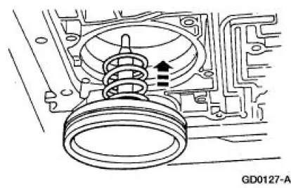
2. Using the special tool, remove the reverse band servo retaining ring.
1. Compress the servo spring.
2. Remove the reverse band servo retaining ring.
3. Remove the reverse servo assembly.
1. Remove the reverse band servo cover.
2. Remove the reverse band servo piston and rod.
3. Remove the reverse band servo spring.
Installation
NOTE: This is not an ordinary installation procedure and does not compensate for band wear.
1. NOTE: Lubricate the reverse piston seal to facilitate assembly and prevent damage to the seal.
Install the reverse servo return spring and piston.
- Do not install the piston cover.
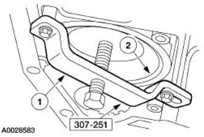
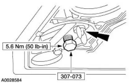
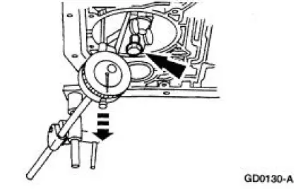
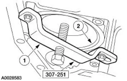
2. Install the special tool and tighten the band apply bolt.
3. Attach the special tool to the transmission.
- Position the indicator stem on the flat portion of the reverse servo piston and zero the dial indicator.
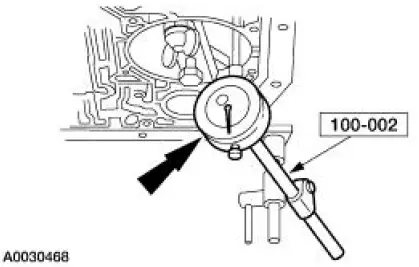
4. Loosen the bolt until the piston stops against the tool.
5. Verify that the amount of piston travel on the dial indicator is within specification.
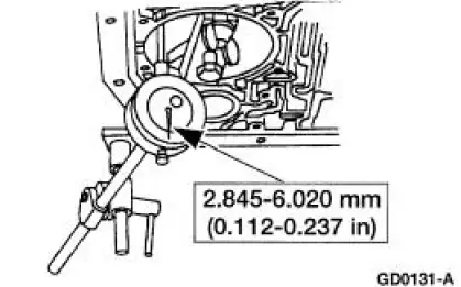
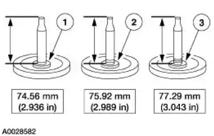
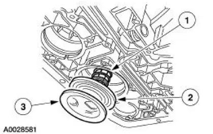
6. If piston travel is not within specification, select and install the correct servo piston assembly to bring the servo piston travel within specification.
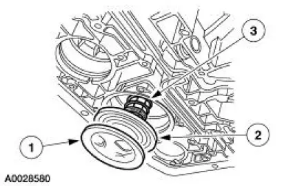
1. One groove
2. Two groove
3. Three groove
7. Remove the dial indicator and servo selection tool.
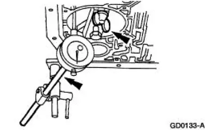
8. Install the correct reverse servo assembly.
1. Install the reverse band servo spring.
2. Install the reverse band servo piston and rod.
3. Install the reverse band servo cover.
9. Using the special tool, install the reverse servo retaining ring.
1. Compress the servo spring.
2. Install the reverse band servo retaining ring.
10. Install the main control valve body. For additional information, refer to Main Control Valve Body in this section.
 Digital Transmission Range (TR) Sensor
Special Tool(s)
Alignment Gauge, TR Sensor
307-351 (T97L-70010-A)
Removal
1. Disconnect the battery ground cable. For additional information, refer
to Section.
2. Raise and suppor ...
 Overdrive Servo
Special Tool(s)
Remover/Installer, Servo
Piston
307-251 (T92P-70023-A)
Removal
1. Remove the main control valve body. For additional information, refer
to Main Control Valve
Body ...
Other materials:
Sensor - Front
Removal
1. Remove the wheel and tire assembly.
2. Remove the inner fender splash shield.
1. Remove the inner fender splash shield push pins.
2. Remove the inner fender splash shield screw.
3. Remove the inner fender splash shield.
3. Remove the front ...
Component Tests
Starter Motor -Voltage Drop Test
WARNING: When servicing starter motor or carrying out other underhood
work in the
vicinity of the starter motor, be aware that the heavy gauge battery input lead
at the starter
solenoid is "electrically hot" at all times. A p ...
Transmission (Disassembly)
Special Tool(s)
Bearing Puller
205-D064 (D84L-1123-A) or
Equivalent
Front Hub Tool
204-069 (T81P-1104-C)
Holding Fixture
307-003 (T57L-500-B)
Impact Slide Hammer
100-001 (T50T-100-A)
Puller
...
