Ford Mustang (1999-2004) Service Manual: Air Conditioning (A/C) System Recovery, Evacuation and Charging
Special Tool(s)
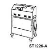 |
R-134a A/C Refrigerant Center 176-00002 or equivalent |
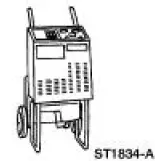 |
R-134a A/C Refrigerant Center 023-00153 or equivalent |
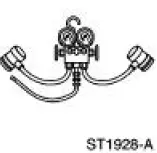 |
R-134a Manifold Gauge Set 176-R032A or equivalent |
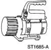 |
1.2 CFM Vacuum Pump 023-00162 or equivalent |
 |
4.0 CFM Vacuum Pump 023-00163 or equivalent |
Refrigerant System Recovery
NOTE: Ford Motor Company recommends use of an A/C service center to carry out recovery, evacuation, and charging of the refrigerant system. If an A/C service center is not available, refrigerant system recovery, evacuation, and charging may be accomplished using a separate recovery station, vacuum pump, charging cylinder, and manifold gauge set.
1. Prior to recovering the refrigerant system, you must verify the purity of the refrigerant. For additional information, refer to Refrigerant Identification Testing in this section.
2. NOTE: Some R-134a service centers require the use of an A/C manifold gauge set. For additional information, refer to Manifold Gauge Set Connection in this section.
Connect an R-134a A/C service center to the low- and high-pressure service gauge port valves.
3. Recover the refrigerant from the system following the operating instructions provided by the equipment manufacturer.
4. Once the service center has recovered the vehicle A/C system refrigerant, close the service center inlet valve (if equipped). Then switch off the power supply.
5. Allow the vehicle A/C system to remain closed for about two minutes. Observe the system vacuum level as shown on the gauge. If the vacuum does not decrease, disconnect the refrigerant center hose(s).
6. If the system vacuum does decrease, repeat Steps 2 through 5 until the vacuum level remains stable for two minutes.
7. Carry out the required repairs.
Refrigerant System Evacuation
NOTE: Ford Motor Company recommends use of an A/C service center to carry out recovery, evacuation, and charging of the refrigerant system. If an A/C service center is not available, refrigerant system recovery, evacuation, and charging may be accomplished using a separate recovery station, vacuum pump, charging cylinder, and manifold gauge set.
1. Connect an R-134a service center to the low- and high-pressure service gauge port valves.
2. Evacuate the system until the low-pressure gauge reads at least 99.4 kPa (29.5 in-Hg) of vacuum and as close to 101.1 kPa (30 in-Hg) as possible. Continue to operate the vacuum pump for a minimum of 45 minutes.
3. Turn off the vacuum pump. Observe the low-pressure gauge for five minutes to make sure that the system vacuum is held. If vacuum is not held for five minutes, leak test the system, service the leak, and evacuate the system again.
Refrigerant System Charging
NOTE: Ford Motor Company recommends use of an A/C service center to carry out recovery, evacuation, and charging of the refrigerant system. If an A/C service center is not available, refrigerant system recovery, evacuation, and charging may be accomplished using a separate recovery station, vacuum pump, charging cylinder, and manifold gauge set.
1. Correctly oil match the system to verify that the correct amount of refrigerant oil is present in the system. For additional information, refer to Refrigerant Oil Adding in this section.
2. Charge the system with the specified amounts of refrigerant oil and refrigerant.
3. When no more refrigerant is being drawn into the system, start the engine and select MAX A/C operation. Adjust the blower motor speed to the maximum and allow the remaining refrigerant to be drawn into the system. Continue to add refrigerant into the system until the specified weight of R-134a has been added. Close the charging cylinder valve and allow the system to pull any remaining refrigerant from the hose. When the low-pressure drops to approximately 207 kPa (30 psi), close the charging hose valve.
 Air Conditioning (A/C) System Flushing
Special Tool(s)
A/C Flush and Purge Machine
219-00022 (part of 219-00023)
or equivalent
A/C Flush and Purge Fitting Kit
219-00024 (part of 219-00023)
or equivalent
WA ...
 Refrigerant System Filtering Following Air Conditioning (A/C) Component
Installation
Refrigerant System Filtering Following Air Conditioning (A/C) Component
Installation
Special Tool(s)
Set, A/C Fittings
412-DS028 (014-00333, D93L-
19703-B) or equivalent
1. Install the new A/C compressor. For additional information, refer to
Section.
2. Install the ...
Other materials:
Air Conditioning (A/C) Compressor Bracket - 3.8L
Removal and Installation
1. Remove the A/C compressor (19703). For additional information, refer to
Air Conditioning (A/C)
Compressor-3.8L in this section.
2. Remove the three bolts and one nut.
3. Remove the A/C compressor mounting bracket.
4. To install ...
Recreational towing
Note: Do not tow with the Shelby GT500 model. It cannot tow a trailer.
Note: Do not exceed the trailer weight for your vehicle configuration
listed in the chart below.
Note: Make sure to take into consideration trailer frontal area. Do not
exceed 12 feet2 (1 ...
Output Shaft
Special Tool(s)
Pinion Bearing Cone Remove
205-D002 (D79L-4621-A) or
Equivalent
Spiral Snap Ring Replacer
308-096 (T85P-7025-A)
Disassembly
1. Using the special tool and a press, remove the third/fourth gear
synchronizer asse ...
