Ford Mustang (1999-2004) Service Manual: Output Shaft
Special Tool(s)
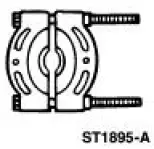 |
Pinion Bearing Cone Remove 205-D002 (D79L-4621-A) or Equivalent |
 |
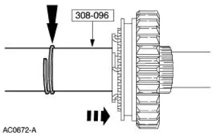
Spiral Snap Ring Replacer 308-096 (T85P-7025-A) |
Disassembly
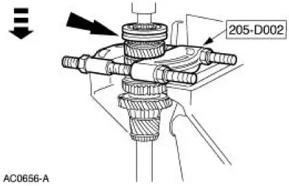
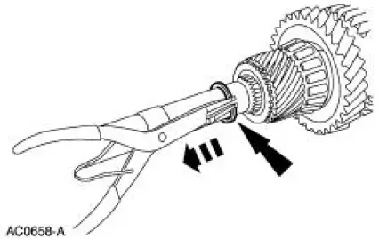
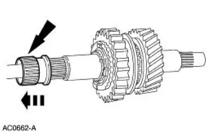
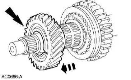
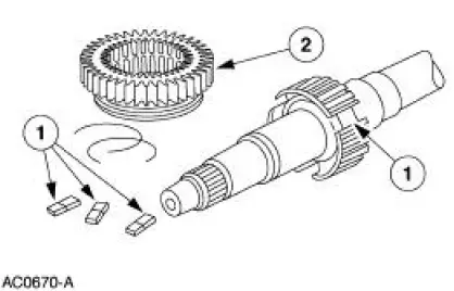
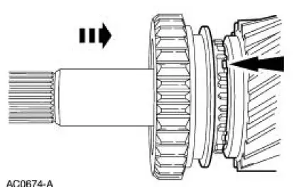
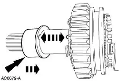
1. Using the special tool and a press, remove the third/fourth gear synchronizer assembly (7124), the third speed synchronizer blocking ring (7107), and the third gear (7B340) as an assembly.
2. Remove the third speed bearing (7B369) and the third speed gear bearing spacer (7B320).
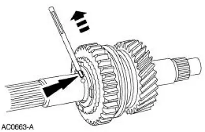
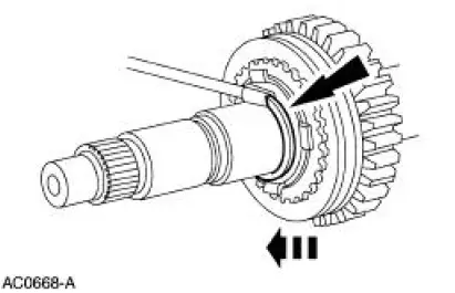
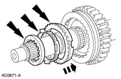
3. Remove the snap ring.
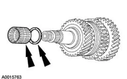
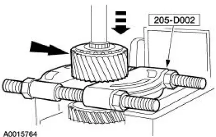
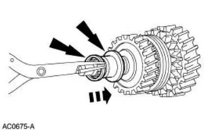
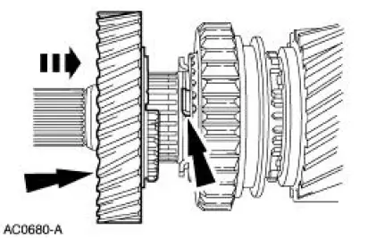
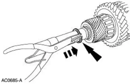
4. Using the special tool and a press, remove the fifth speed driven gear (7K316).
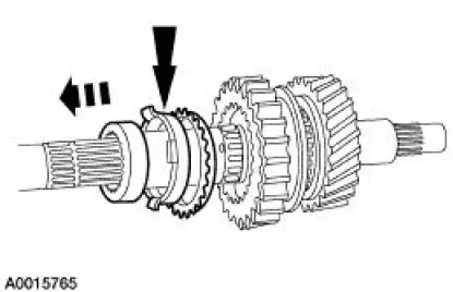
5. Remove the output shaft rear bearing (7065).
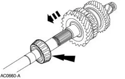
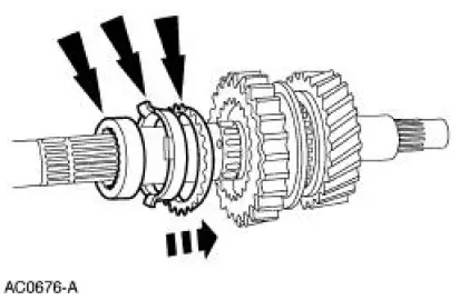
6. Remove the first gear (7100).
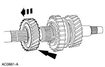
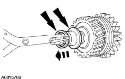
7. NOTE: The first gear bearing spacer (7173) fits snugly on the output shaft assembly (7061).
Remove the first gear bearing (7127) and the spacer as an assembly.
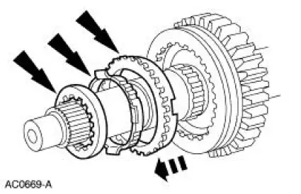
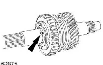
8. Remove the first and second speed synchronizer hub ball (7K218).
9. Remove the first speed synchronizer inner cone (7175), the first speed synchronizer outer cone (7174), and the first speed synchronizer blocking ring (7107) as an assembly.
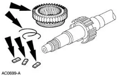
10. Remove the snap ring and the thrust washer (7119).
11. Remove the second gear (7102), the second speed bearing (7B369), and the second speed gear bearing spacer (7728).
12. Remove the output shaft bearing snap ring and the second speed synchronizer thrust washer (7117).
13. Remove the second speed synchronizer inner cone (7175), the second speed synchronizer outer cone (7174), and the second speed synchronizer blocking ring (7107) as an assembly.
14. Remove the first and second gear synchronizer sliding sleeve (7124).
15. CAUTION: Note the orientation of the synchronizer hub insert springs (7109) and the synchronizer hub inserts (7A044) for assembly reference.
NOTE: The first and second gear synchronizer sliding sleeve, the hub, and the output shaft are an assembly. Do not attempt to separate the hub from the output shaft. Only the synchronizer hub insert springs and the synchronizer hub inserts are available separately.
Remove the synchronizer hub insert springs and the hub inserts.
Assembly
1. Soak the blocking rings in transmission fluid for ten minutes.
- Use MERCON Multi-Purpose ATF Transmission Fluid XT-2-QDX or equivalent.
2. Assemble the first and second synchronizer.
1. Install the synchronizer hub insert springs and the synchronizer inserts into the synchronizer hub.
2. Install the sliding sleeve onto the hub.
3. NOTE: If not done so previously, soak the blocking ring in MERCON Multi-Purpose ATF Transmission Fluid XT-2-QDX or equivalent for ten minutes.
NOTE: Align the slots in the synchronizer blocking ring with the tabs in the first and second speed synchronizer.
Install the second speed synchronizer blocking ring and the inner and outer cones as an assembly.
4. Install the second speed synchronizer thrust washer.
5. Using the special tool, install the output shaft bearing snap ring.
6. Install the second speed gear bearing spacer and the second speed bearing.
7. NOTE: Align the slots in the second gear with the tabs on the synchronizer blocking ring.
Install the second gear onto the output shaft.
8. Install the thrust washer and the snap ring.
9. NOTE: If not done so previously, soak the blocking ring in MERCON Multi-Purpose ATF Transmission Fluid XT-2-QDX or equivalent for ten minutes
NOTE: Align the slot in the synchronizer blocking ring with the tab on the first and second synchronizer.
Install the first speed synchronizer blocking ring and the inner and outer cones as an assembly.
10. Install the first and second speed synchronizer hub ball.
11. NOTE: Align the notch in the first gear bearing spacer with the first and second speed synchronizer ball.
Install the first gear bearing spacer and the first gear bearing.
12. NOTE: Align the slots on the synchronizer blocking ring with the slots on the first gear.
Install the first gear.
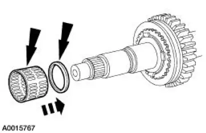
13. Install the output shaft rear bearing.
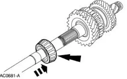
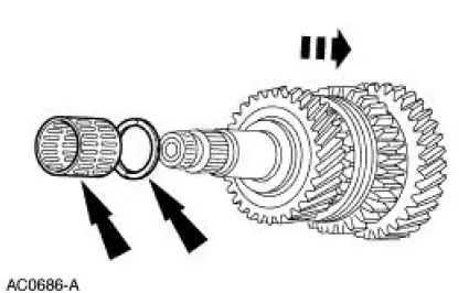
14. Lubricate the splines of the fifth speed driven gear with petroleum jelly.
15. CAUTION: Align the output shaft splines and the splines of the fifth speed driven gear or damage will occur.
Position the fifth speed driven gear on the output shaft. Using a press and a capped length of pipe 31.7 mm (1.26 in) inside diameter X 356 mm (14.24 in) long, install the fifth speed driven gear.
16. Install the snap ring.
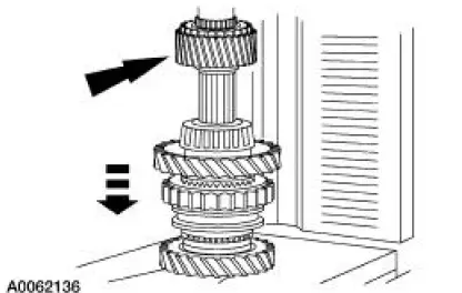
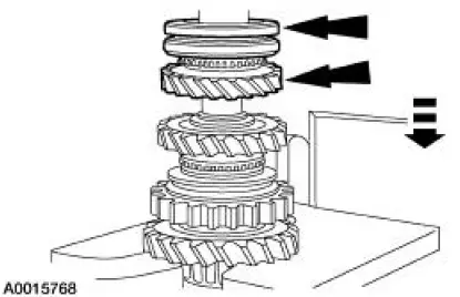
17. Install the third speed gear bearing spacer and the third speed bearing.
18. CAUTION: Before pressing the components together, verify that the synchronizer hub faces the short end of the output shaft. Hold the third gear against the synchronizer to maintain the synchronizer blocking ring alignment.
NOTE: If not done so previously, soak the blocking ring in MERCON Multi-Purpose ATF Transmission Fluid XT-2-QDX or equivalent for ten minutes.
Using a 1-1/2 inch deep well socket and a press, install the third gear, the third speed synchronizer blocking ring, and the third/fourth gear synchronizer assembly.
 Input Shaft and Bearing
Special Tool(s)
Input Shaft Seal Replacer
308-220 (T94P-7025-AH)
Pinion Bearing Cone Remover
205-D002 (D79L-4621-A) or
Equivalent
Disassembly
1. Using the special tool ...
 Countershaft Bearing
Special Tool(s)
Bearing Replacer
308-061 (T77J-7025-L)
Front Bearing Replacer
308-062 (T77J-7025-M)
Mainshaft Front Bearing
Replacer
308-081 (T82T-7003-DH)
...
Other materials:
Installation
1. NOTE: Inspect the spring insulators for wear or damage. Install new
spring insulators if
necessary.
Make sure the spring insulators are correctly installed on the springs.
2. Install the springs.
1. Position the springs.
2. Raise the subframe using ...
Removal
CAUTION: Since the engine is not free-wheeling, if the crankshaft or
the camshafts are
moved in any manner during removal and installation, the crankshaft and the
camshafts must
be re-synchronized.
1. Remove the engine front cover. For additional informatio ...
Switch - Speed Control Actuator
Removal
1. Remove the steering wheel; refer to Section.
2. Remove the steering wheel rear cover.
1. Remove the screws.
2. Remove the steering wheel rear cover.
3. Remove the ribbon harness from the clips.
4. Remove the horn contact electrical c ...
