Ford Mustang (1999-2004) Service Manual: Assembly
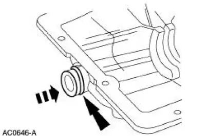
1. Install the new O-ring.
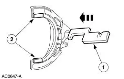
2. Assemble the gear shifter forks.
1. Install the gear shift plate into the gear shifter fork.
2. Install the gear shift fork inserts.
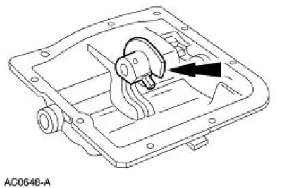
3. NOTE: Position the narrow side of the C-shaped gear selector interlock sleeve in the case cover slot. Position the roll pin hole in the selector body toward the rear of the cover.
Install the gear selector interlock sleeve and the selector body as an assembly.
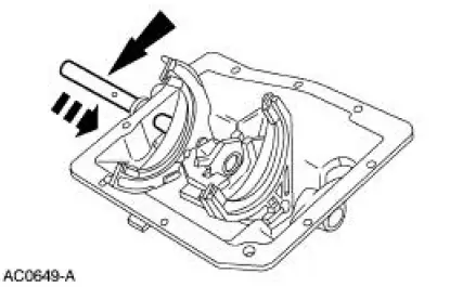
4. Lubricate the main shift control shaft with petroleum jelly.
5. NOTE: The 1-2 gear shifter fork is the larger shifter fork. The gear shifter fork offset lever must face the cover. Position the gear shift plate attached to the 3-4 gear shifter fork under the gear shift plate attached to the 1-2 gear shifter fork.
Position the gear shifter forks and the main shift control shaft in the cover.
- Slide the shaft through the cover and shift the components until the shaft stops against the cover.
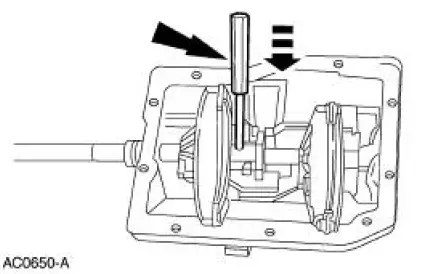
6. CAUTION: Install the pin slightly below the selector body surface. Failure to countersink the pin may result in interference between the pin and the gear selector interlock sleeve during shifts.
NOTE: The flat on the main shift control shaft must face upward.
Install the pin.
 Disassembly
1. NOTE: Mark the position of each gear shifter fork (7230).
Place the gear shift plates (7N232) and the gear selector interlock sleeve
(7K201) in the neutral
position to center the gear shift pl ...
 Input Shaft and Bearing
Special Tool(s)
Input Shaft Seal Replacer
308-220 (T94P-7025-AH)
Pinion Bearing Cone Remover
205-D002 (D79L-4621-A) or
Equivalent
Disassembly
1. Using the special tool ...
Other materials:
Inspection and Verification
WARNING: Batteries contain sulfuric acid. Avoid contact with
skin, eyes, or clothing.
Also, shield your eyes when working near batteries to protect against
possible splashing of the
acid solution. In case of acid contact with skin or eyes, flush
...
Refrigerant Identification Testing
Special Tool(s)
Refrigerant Identifier with Air-
Radicator
198-00003 or equivalent
1. NOTE: An A/C refrigerant analyzer must be used to identify gas
samples taken directly from the
refrigeration system or storage containers prior to recoveri ...
Transmission Case
Special Tool(s)
Handle
205-D055 (D81L-4000-A)
Installer, Bearing Cup
204-039 (T77F-1217-B)
Installer, Drive Pinion Bearing
Cup
205-054 (T71P-4616-A)
Installer, Rear Axle Oil Seal
205-155 (T80T-4000-Y)
...
