
Ford Mustang (1999-2004) Service Manual: Assembly
1. Lubricate the differential side gear thrust washers and the differential side gear journals, and assemble the washers to the gears.
- Use SAE 75W-140 High Performance Rear Axle Lubricant F1TZ-19580-B or equivalent meeting Ford specification WSL-M2C192-A.
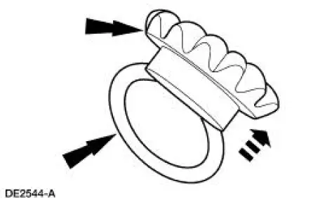
2. Lubricate the differential pinion thrust washers and the differential pinion gears, and assemble the washers to the gears.
- Use SAE 75W-140 High Performance Rear Axle Lubricant F1TZ-19580-B or equivalent meeting Ford specification WSL-M2C192-A.
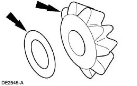
3. Position the differential side gear and thrust washer assemblies in the differential case.
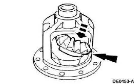
4. Engage the differential pinion gears with the differential side gears and rotate the pinion gears to align with the differential pinion shaft bore.
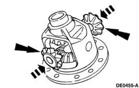
5. Insert the differential pinion shaft.
- Align the hole in the differential pinion shaft with the hole in the differential case.
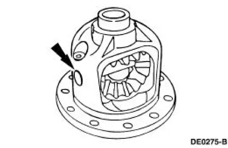
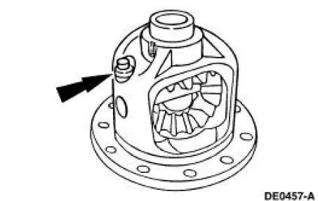
6. Install a new bolt finger-tight.
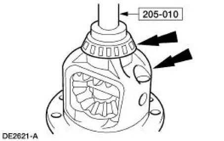
7. Using the special tool, install the new differential bearings, if removed.
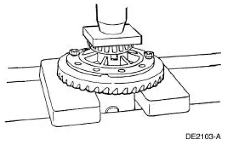
8. Position the ring gear and the differential case. Align the bolt holes by starting two bolts through the holes in the differential case and the ring gear. Press the ring gear on the differential case.
9. Install the bolts.
- Apply Stud and Bearing Mount EOAZ-19554-BA or equivalent meeting Ford specification WSK-M2G349-A1 to the bolt threads.
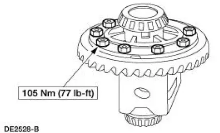
10. Install the differential assembly. For additional information, refer to Differential Case in this section.
 Disassembly
1. Remove the differential assembly from the differential housing. For
additional information, refer
to Differential Case in this section.
2. Remove the bolts.
3. CAUTION: Do not damage the thread ...
 Differential Case and Ring Gear - Traction-Lok
Special Tool(s)
2-Jaw Puller
205-D072 (D97L-4221-A) or
equivalent
Gauge, Differential Clutch
205-022 (T66L-4204-A)
Gauge, Differential Clutch
205-135 (T80P-4946-A)
...
Other materials:
Handles, Locks, Latches And Mechanisms (Description and Operation)
Lock Cylinders
Individual lock cylinders are repaired by discarding the inoperative
lock cylinder and building a new
lock cylinder using the appropriate lock repair package. The lock repair
package includes a detailed
instruction sheet to build the ...
Timing Chain
Removal
1. Remove the timing cover. For additional information, refer to Engine
Front Cover in this section.
2. Remove the camshaft position sensor drive gear.
1. Remove the bolt.
2. Remove the camshaft position sensor drive gear.
3. Rotate the ...
Engine Ignition (Description and Operation)
Eight separate ignition coils:
are controlled by the powertrain control module (PCM).
are mounted directly above each spark plug.
are controlled by the powertrain control module for correct firing
sequence.
The spark plug:
changes the high vo ...
