Ford Mustang (1999-2004) Service Manual: Assembly
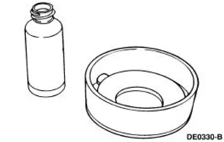
1. CAUTION: 118 ml (4 oz) of the specified Ford Friction Modifier must be used in the axle.
Lubricate each steel clutch plate and soak all friction plates for no less than 15 minutes.
- Use Additive Friction Modifier C8AZ-19B546-A or equivalent meeting Ford specification EST-M2C118-A
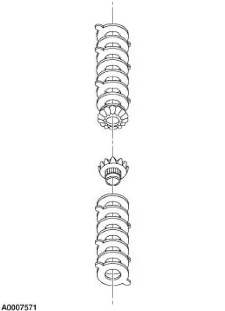
2. CAUTION: Do not mix the differential clutch packs or shims from one side with the other.
Assemble the differential clutch packs (without the shims) on their respective differential side gears.
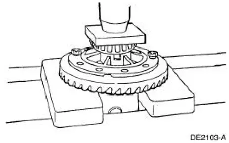
3. Place the base portion of the special tool in a vise. Install the differential differential side gear and differential clutch pack (without the shim) on the tool.
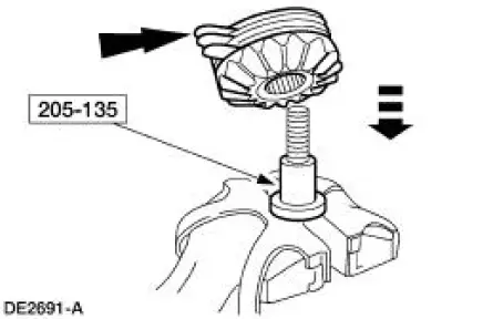
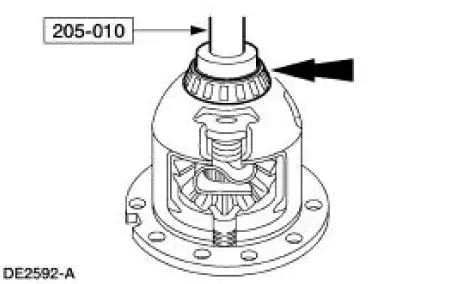
4. Position the special tool hand-tight on top of the differential clutch pack.
5. Install the special tool over the disc and differential clutch pack.
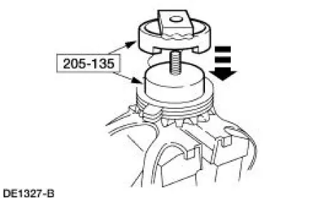
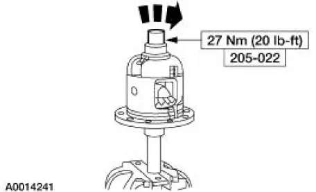
6. Install the nut.
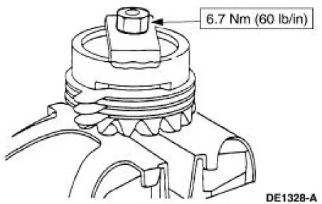
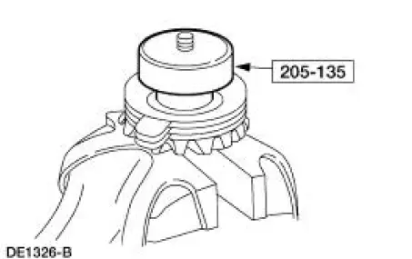
7. NOTE: Clutch Pack Rebuild Kit F5AZ-4947-A is available for this application.
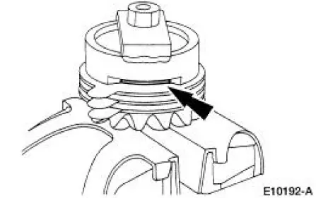
Select and insert the thickest feeler gauge blade that will enter between the tool and the differential clutch pack. The reading will be the thickness of the new clutch shim.
Selective Shims
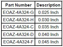
8. Remove the special tools from the differential clutch pack and differential side gear assembly.
9. Install shim(s) on the differential clutch pack and differential side gear assembly.
10. Install the differential side gear assemblies in the differential case.
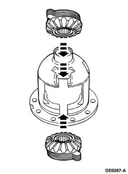
11. Install the differential pinion gear and differential pinion thrust washer assemblies in the differential case.
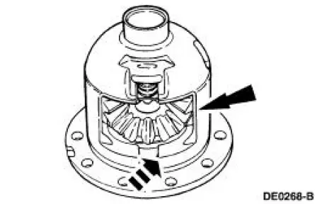
12. Using a soft-faced hammer, install the differential clutch spring.
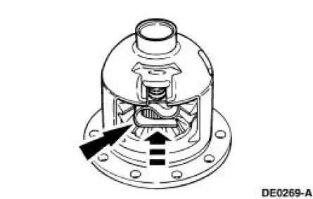
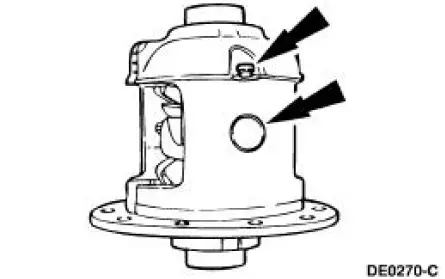
13. Install the differential pinion shaft and install a new bolt finger-tight.
14. Mount the differential case and the special tool in a vise. Using the special tool, check the torque necessary to rotate one differential side gear.
- If reusing the original clutch plates, the initial minimum break-away torque must be no less than the specification. The minimum rotating torque necessary to keep the differential side gear turning with new clutch plates may vary.
15. Using the special tool, install the differential bearings, if removed.
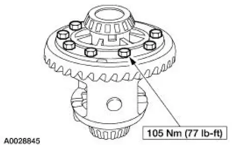
16. Position the differential ring gear and the differential case. Align the bolt holes by starting two bolts through the holes in the differential case and the differential ring gear. Press the differential ring gear on the differential case.
17. Install the bolts.
- Apply Stud and Bearing Mount EOAZ-19554-BA or equivalent meeting Ford specification WSK-M2G349-A1 to the bolt threads.
18. Install the differential assembly in the differential housing. For additional information, refer to Differential Case in this section.
 Disassembly
1. Remove the differential assembly from the differential housing. For
additional information, refer
to Differential Case in this section.
2. Remove the 10 bolts.
3. CAUTION: Do not damage the thr ...
 Rear Drive Axle/Differential - Ford 8.8-Inch IRS
General Specifications
Torque Specifications
a: Use Stud and Bearing Mount EOAZ-19554-BA or equivalent meeting Ford
specification WSKM2G349-
A1.
b: With pinion flange yoke seal. ...
Other materials:
Camshaft End Play - OHC Engines
Special Tool(s)
Dial Indicator Gauge with
Holding Fixture
100-002 (TOOL-4201-C) or
equivalent
1. Remove the roller followers. Refer to the appropriate section in Group 303
for the procedure.
2. Use a Dial Indicator Gauge with Holding Fixt ...
Pinpoint Tests
CAUTION: Be careful when probing the CJB, battery junction box (BJB)
or any
connectors. Damage will result to the connector receptacle if the probe or
terminal being used
is too large.
CAUTION: Electronic modules are sensitive to static electrical char ...
Exterior Lighting
Torque Specifications
Exterior Lighting
The exterior lighting system consists of the following components:
headlamps (13008)
parking lamps
rear lamps (13404)
high mounted stoplamp
license lamps
front turn lamps
reversing lamps
fog ...
