
Ford Mustang (1999-2004) Service Manual: Disassembly
1. Remove the differential assembly from the differential housing. For additional information, refer to Differential Case in this section.
2. Remove the 10 bolts.
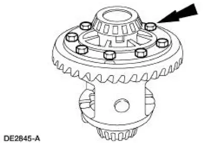
3. CAUTION: Do not damage the threads in the bolt holes.
Insert a punch in the bolt holes, and drive off the ring gear.
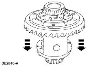
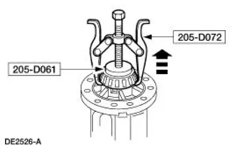
4. Using the special tools, remove the differential bearings (4221), if necessary.
5. Remove the bolt and the differential pinion shaft (4211).
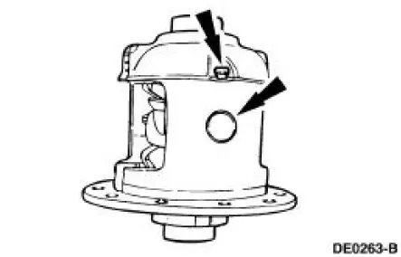
6. WARNING: Due to the spring tension, use care when removing the differential clutch spring (4214). Failure to follow these instructions may result in personal injury.
Remove the differential clutch spring.
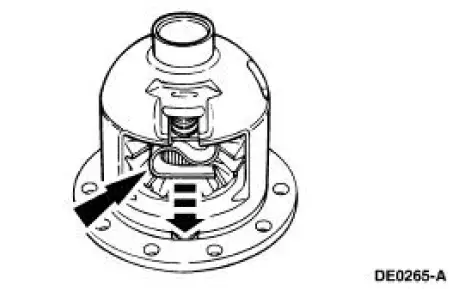
7. Remove the differential gears.
1. Remove the two differential pinion gears (4215).
2. Remove the two differential side gears (4236).
3. Remove the two differential pinion thrust washers (4230).
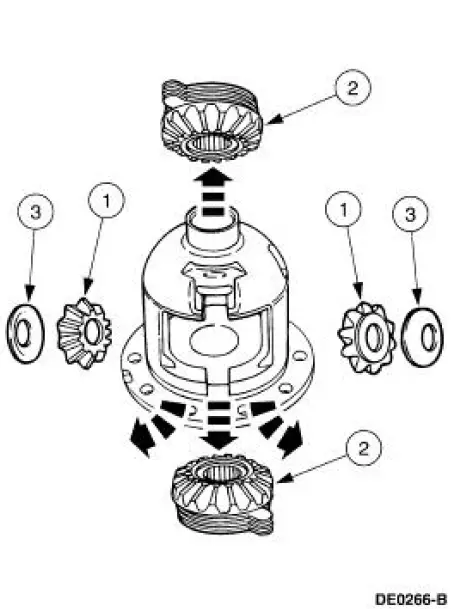
8. CAUTION: Keep the differential clutch packs (4947) in order. Do not mix them.
Always reassemble them in the same sequence.
Separate the differential clutch packs and shims from the differential side gears and tag them "right" and "left".
- Clean and inspect the remaining differential components for wear and damage and install new parts as necessary.
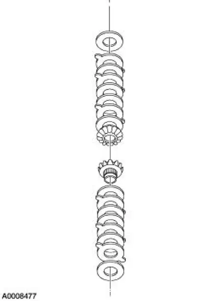
9. CAUTION: Do not use acids or solvents when cleaning the differential clutch pack.
Wipe components only with a clean, lint-free cloth.
Clean and inspect the differential clutch packs for wear and damage and install new parts as necessary.
 Differential Case and Ring Gear - Traction-Lok
Special Tool(s)
2-Jaw Puller
205-D072 (D97L-4221-A) or
equivalent
Gauge, Differential Clutch
205-022 (T66L-4204-A)
Gauge, Differential Clutch
205-135 (T80P-4946-A)
...
 Assembly
1. CAUTION: 118 ml (4 oz) of the specified Ford Friction Modifier must
be used in the
axle.
Lubricate each steel clutch plate and soak all friction plates for no less than
15 minutes.
Use Additiv ...
Other materials:
Fuel quality
Note: Use of any fuel other than those recommended may cause
powertrain damage and a loss of vehicle performance; repairs may not be
covered under warranty.
Choosing the Right Fuel
Use only unleaded fuel or unleaded fuel blended with a maximum of
15% ethanol. ...
Spindle
Special Tool(s)
Tie-Rod End Remover
211-001 (TOOL-3290-D) or
Equivalent
Removal
CAUTION: Suspension fasteners are critical parts because they affect
performance of vital
components and systems and their failure can result in major service expen ...
Disassembly
Initial disassembly
1. Remove the differential housing cover (4033) and drain the lubricant into
a suitable container.
2. Wipe the lubricant from the internal working parts and inspect the parts for
wear and damage.
3. Using the special tool, measure and n ...
