Ford Mustang (1999-2004) Service Manual: Assembly
Initial assembly
1. Coat the new differential drive pinion bearing cup(s) with lubricant.
- Use SAE 75W-140 High Performance Rear Axle Lubricant F1TZ-19580-B or equivalent meeting Ford specification WSL-M2C192-A.
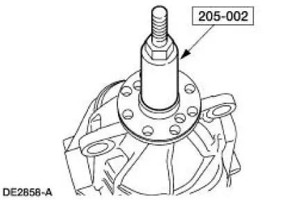
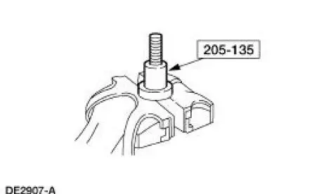
2. Using the special tool, install the differential drive pinion bearing cup(s).
1. Position the bearing cup(s) on the special tool.
2. Position the special tool and the bearing cup(s) in the differential housing.
3. Tighten the special tool to fully seat the bearing cup(s) in the bore(s).
3. NOTE: Apply a light film of SAE 75W-140 High Performance Rear Axle Lubricant F1TZ-19580- B or equivalent meeting Ford specification WSL-M2C192-A on the front and rear pinion bearings.
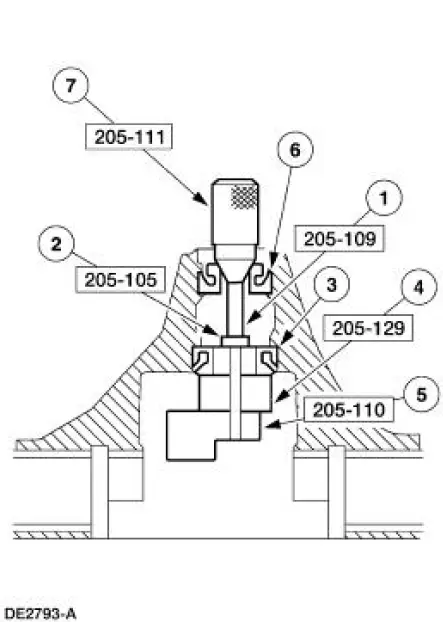
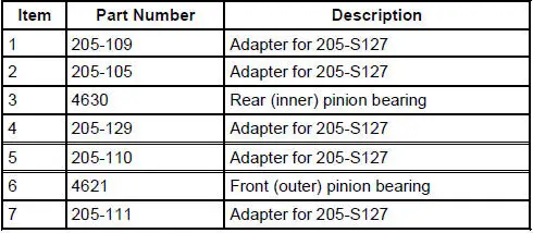
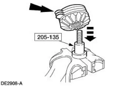
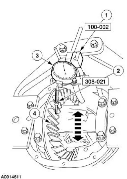
Install the pinion bearings and special tools as shown.
4. NOTE: This step duplicates pinion bearing preload.
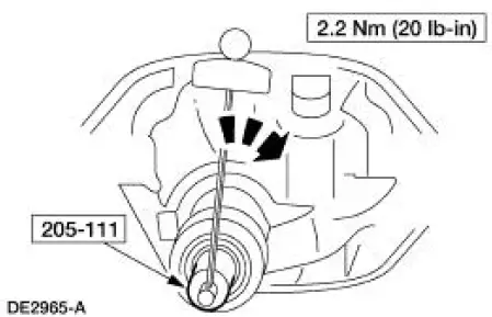
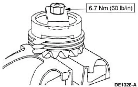
Thread the special tool onto the Screw and tighten to the specification shown.
5. CAUTION: Offset the special tool to obtain an accurate reading.
Rotate the special tool several half turns to seat the pinion bearings. Position the special tool as shown.
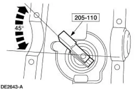
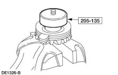
6. Install the special tool.
1. Position the special tool on the differential housing differential bearing seat.
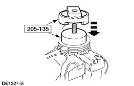
2. Install the differential bearing caps.
3. Install the bolts.
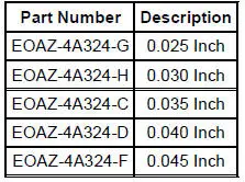
7. Use a drive pinion bearing adjustment shim as a gauge for shim selection. Check the drive pinion bearing adjustment shim thickness between the Gauge Block and the Gauge Tube. A slight drag indicates correct shim selection.
8. Remove all of the special tools.
9. CAUTION: Use the same pinion bearings and drive pinion bearing adjustment shim from the drive pinion bearing adjustment shim selection procedure for final assembly.
Position the drive pinion bearing adjustment shim and the pinion bearing on the drive pinion gear stem.
10. Using the special tools and a suitable press, firmly seat the drive pinion bearing adjustment shim and pinion bearing on the drive pinion gear stem.
11. Install the front pinion bearing and the rear axle drive pinion shaft oil slinger in the differential housing.
12. CAUTION: Installation without the correct tool can result in early seal failure.
CAUTION: If the seal becomes misaligned during installation, remove it and install a new one.
NOTE: Coat the rear axle drive pinion seal lips with Premium Long-Life Grease XG-1-C or equivalent meeting Ford specification ESA-M1C75-B.
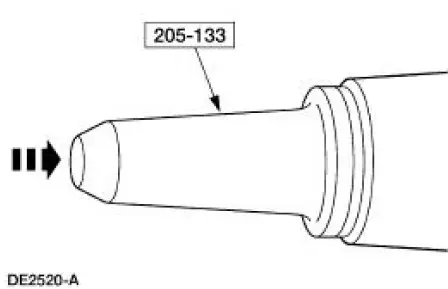
Using the special tool, install the new rear axle drive pinion seal.
13. CAUTION: Make sure the splines on the drive pinion gear stem are free of burrs. If burrs are evident, remove them using a fine crocus cloth, work in a rotational motion.
Place a new differential drive pinion collapsible spacer on the drive pinion gear stem against the pinion stem shoulder.
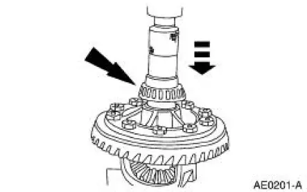
14. Install the drive pinion gear with the differential drive pinion collapsible spacer in the differential housing.
15. NOTE: Disregard the index marks if installing a new rear axle pinion flange.
Position the rear axle pinion flange.
1. Lubricate the rear axle pinion flange splines.
- Use SAE 75W-140 High Performance Rear Axle Lubricant F1TZ-19580-B or equivalent meeting Ford specification WSL-M2C192-A.
2. Position the rear axle pinion flange.
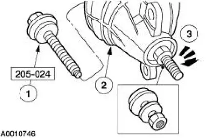
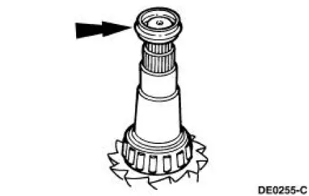
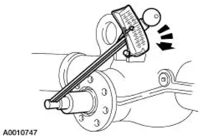
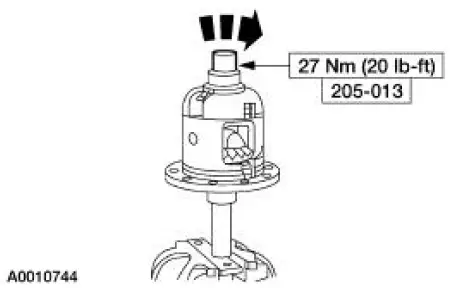
16. Using the special tool, install the rear axle pinion flange.
17. CAUTION: Do not under any circumstance loosen the nut to reduce preload. If it is necessary to reduce preload, install a new differential drive pinion collapsible spacer and nut.
Tighten the nut to set the preload.
- Rotate the pinion occasionally to make sure the pinion bearings seat correctly. Take frequent pinion bearing torque preload readings by rotating the drive pinion gear with a Nm (inch/pound) torque wrench.
- For new pinion bearings, tighten the nut to specification. Refer to torque specifications for new pinion bearings in the Specifications portion of this section.
- For used pinion bearings, if the preload recorded prior to disassembly is lower than the specification for used bearings, then tighten the nut to specification. Refer to torque specifications for used pinion bearings in the Specifications portion of this section.
- For used pinion bearings, if the preload recorded prior to disassembly is higher than the specification for used bearings, then tighten the nut to the original reading as recorded.
18. CAUTION: 118 ml (4 oz) of Additive Friction Modifier C8AZ-19B546-A or equivalent meeting Ford specification EST-M2C118-A must be used in the axle.
Lubricate each steel clutch plate and soak all friction plates for no less than 15 minutes.
- Use Additive Friction Modifier C8AZ-19B546-A or equivalent meeting Ford specification EST-M2C118-A.
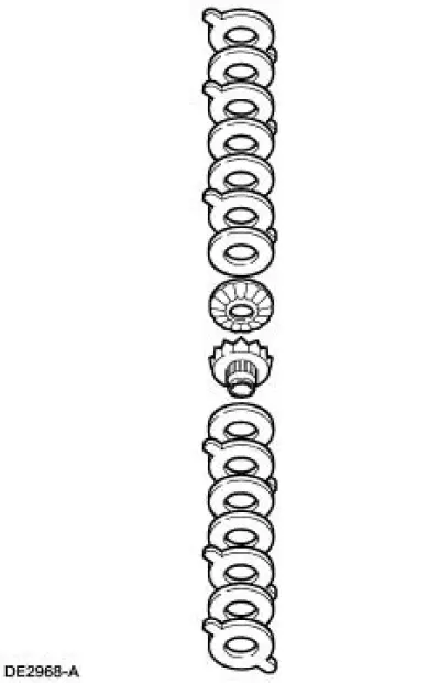
19. CAUTION: Do not mix the clutch plates, clutch discs or shim from one side with the other.
Assemble the differential clutch packs (without the shims) on their respective differential side gear.
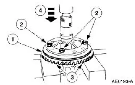
20. Place the base portion of the special tool in a vise.
21. Install the differential clutch pack and differential side gear (without the shim) on the special tool.
22. Position the special tool hand-tight on top of the differential clutch pack.
23. Install the special tool over the disc and differential clutch pack.
24. Install the nut.
25. Select and insert the thickest feeler gauge blade that will enter between the tool and the differential clutch pack. The reading will be the thickness of the new clutch shim.
Selective Shims
26. Remove the special tool from the differential clutch pack and differential side gear assembly.
27. Install the shim(s) on the differential clutch pack and differential side gear assembly.
28. Install the differential side gear assemblies in the differential case.
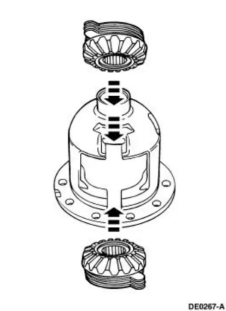
29. Install the differential pinion gear and differential pinion thrust washer assemblies in the differential case.
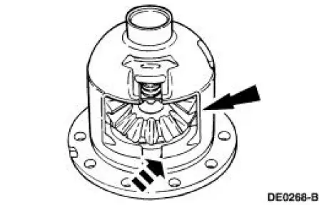
30. Using a soft-faced hammer, install the differential clutch spring.
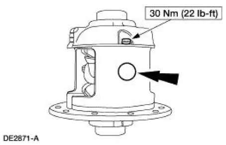
31. NOTE: If a new bolt is unavailable, coat the original bolt threads with Threadlock and Sealer EOAZ-19554-AA or equivalent meeting Ford specification WSK-M2G351-A5 prior to final installation.
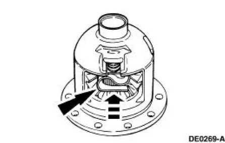
Install the differential pinion shaft and install a new bolt finger-tight.
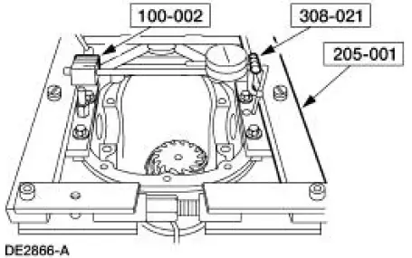
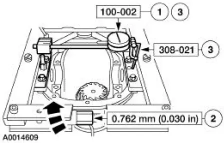
32. Mount the differential case and the special tool in a vise. Using the special tool, check the torque necessary to rotate one differential side gear.
- If reusing the original clutch plates, the initial minimum break-away torque must be no less than the specification. The minimum rotating torque necessary to keep the differential side gear turning with new clutch plates may vary.
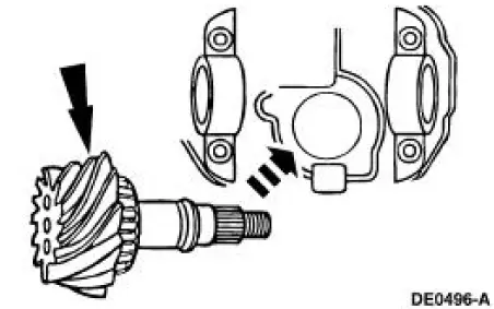
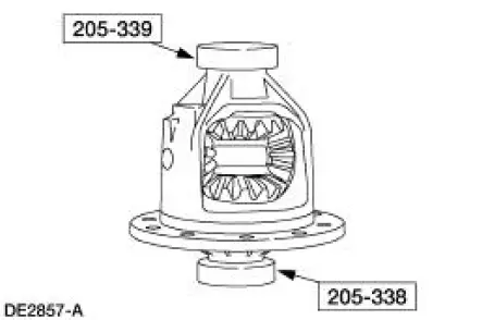
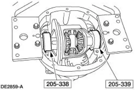
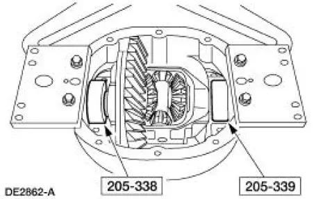
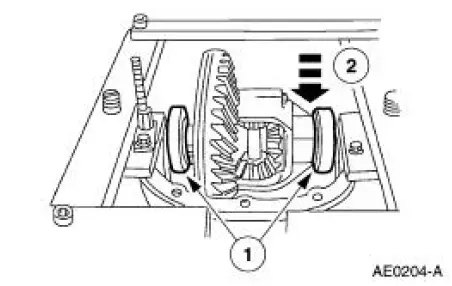
33. CAUTION: The Master bearings are marked LH and RH. Install them as shown.
Install the special tools on the differential case.
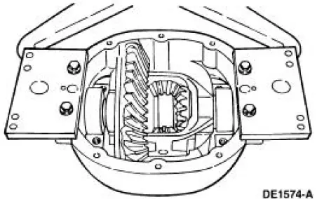
34. CAUTION: Do not damage the aluminum differential housing while carrying out these procedures.
Place the differential case with the special tools in the differential housing.
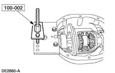
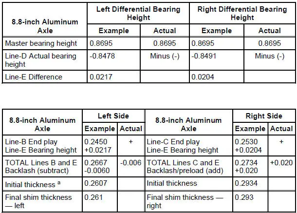
35. Position the special tool on the outside mounting hole.
36. NOTE: Repeat this step until obtaining a consistent reading.
Measure the total end play.
1. Attach the special tool and position the indicator tip on the machined surface of the differential case flange.
2. Move the differential case to the left and the right (as far as possible).
3. Record the reading on the differential bearing shim selection procedure line A.
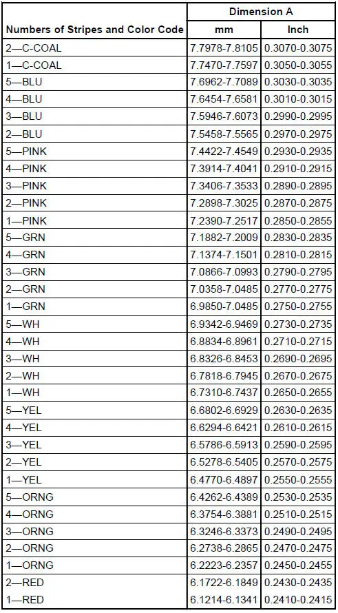
Differential Bearing Shim Selection Chart
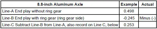
a: Round off initial thickness to the nearest shim thickness as in example for final shim thickness.
37. Remove the Dial Indicator and the differential case from the differential housing.
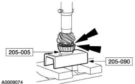
38. Draw-file the differential ring gear mounting surface to remove any nicks or burrs.
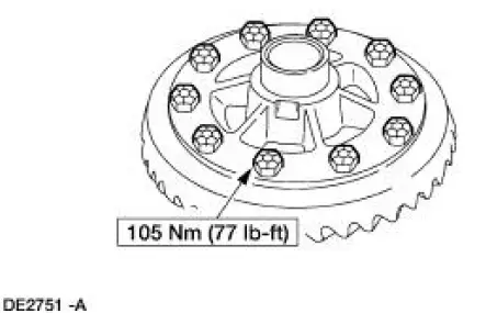
39. Install the differential ring gear.
1. Place the differential ring gear on the differential case.
2. Hand start three bolts to align the holes in the differential ring gear and the differential case.
3. Place the differential case and differential ring gear onto the press bed blocks with the differential ring gear teeth facing downward.
4. Press the differential ring gear into place.
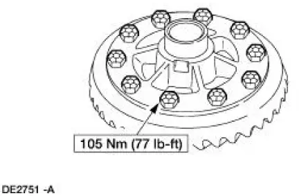
40. Install the remaining bolts.
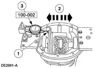
41. Place the differential case with the special tools into the differential housing.
42. NOTE: The bolts retaining the differential ring gear to the differential case may interfere while carrying out this procedure. If so, remove three to five bolts to provide clearance.
Measure the end play.
1. Attach the special tool and position the indicator tip on the machined surface of the differential case flange.
2. Rock the differential ring gear to allow full mesh with the drive pinion gear.
3. With the gears in full mesh, set the special tool to zero.
4. Move the differential case as far as possible to the left and note the reading.
5. Record the reading on the differential bearing shim selection procedure line B.
- Remove the special tool.
43. Remove the differential case from the differential housing.
44. Remove the bolts. Apply Stud and Bearing Mount EOAZ-19554-BA or equivalent meeting Ford specification WSK-M2G349-A1 to the bolt threads, and reinstall the bolts.
45. NOTE: Measure the stand height of both differential bearings prior to installation.
NOTE: Mark the differential bearings left and right before measuring them.
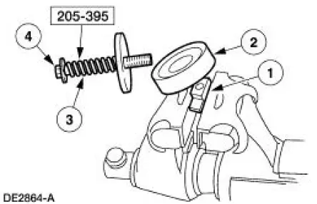
Install the special tool.
1. Place the special tool base in a soft-jawed vise with the bearing mounting surface above the vise jaws.
2. Position the differential bearing on the special tool base.
3. Attach the bolt, spring, washers and spacer.
4. Tighten the bolt.
46. Measure the differential bearing stand height.
1. Invert the special tool and clamp the bolt head in a vise.
2. Position a depth micrometer flat on the differential bearing.
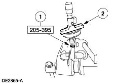
47. Measure both differential bearings stand height. Record the measurement on the differential bearing shim selection procedure line D.
48. Press the left and right differential bearing on the differential case.
49. Install the special tools.
50. CAUTION: Overspreading may damage the differential housing.
NOTE: Tighten and loosen the Differential Carrier Spreader screw to normalize the Housing Spreader Adapters prior to taking the final Dial Indicator reading.
Spread the differential housing to the specification.
1. Adjust the special tool to zero.
2. Tighten the screw until spreading the differential housing to the specification.
3. Remove the special tools.
51. NOTE: Select the correct size differential bearing shims by completing the differential bearing shim selection chart.
NOTE: Apply a light coating of Premium Long-Life Grease XG-1-C, or equivalent meeting Ford specification ESA-M1C75-B to the differential bearing shim to help hold in place.
Place the differential bearing shims in the differential housing.
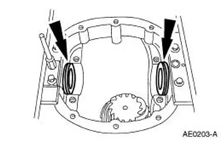
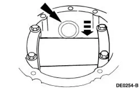
52. Install the differential case.
1. Position the differential bearing cups on the differential bearings.
2. Lower the differential case in place between the differential bearing shims.
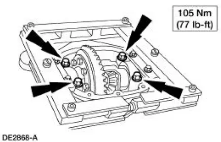
53. NOTE: Tighten the bolts prior to releasing the carrier spreader.
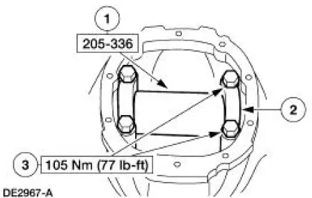
Install the differential bearing caps in their original locations and positions and tighten the bolts.
54. Remove the special tool.
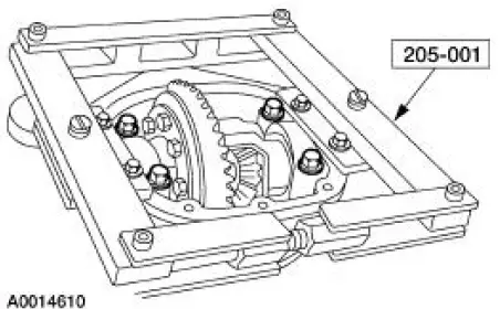
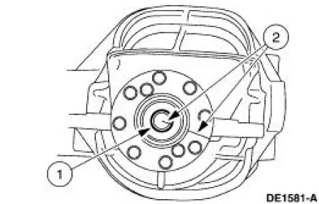
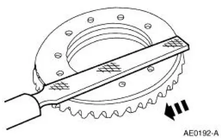
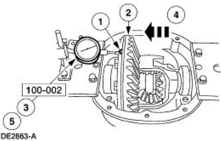
55. Install the special tool at the 12 o'clock position.
56. Using the special tools, measure the differential ring gear backlash at four equally spaced points.
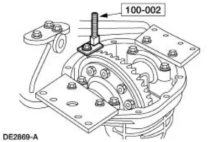
1. Attach the special tool.
2. Position the special tool tip centrally on a drive tooth.
3. Zero the indicator.
4. Turn the differential ring gear without turning the drive pinion gear. Record the indicator reading. The allowable backlash is 0.203 mm ( 0.008 in) to 0.330 mm ( 0.013 in) and must not very more than 0.1016 mm (0.004 in) between points measured. A backlash variation of more than 0.1016 mm (0.004 in) between points checked indicates gear/case runout.
- If backlash is within specifications, proceed to Final assembly in this procedure.
- To correct for a high or low backlash proceed as follows.
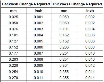
57. To correct for high or low backlash increase the thickness of one differential bearing shim and decrease the thickness of the other differential bearing shim by the same amount. Refer to the following tables when adjusting the backlash. When the backlash is within specifications, proceed to Final assembly in this procedure.
Differential Shim Size Chart - 4067 -
 Final disassembly
32. If not done previously, remove the bolts.
33. CAUTION: Do not damage the bolt hole threads.
If not done previously, insert a punch in the bolt holes and drive off the
differential ring gear.
...
Other materials:
Diagnosis By Symptom
Special Tool(s)
Transmission Fluid Pressure
Gauge
307-004 (T57L-77820-A)
Air Test Plate, Transmission
307-246 (T92P-7006-A)
Breakout Box, EEC-V Control
System
418-049 (T94L-50-EEC-V) or
equivalent
MLP- ...
Transmission fluid check
Checking Automatic Transmission Fluid
Note: Transmission fluid should be checked and, if required, added by
an authorized dealer.
The automatic transmission does not have a transmission fluid dipstick.
See your Scheduled Maintenance Information for scheduled ...
Radiator
Material
Item
Specification
Motorcraft Premium Gold
Engine Coolant
VC-7-A (in Oregon VC-7-B)
(yellow color)
WSS-M97B51-
A1
Removal and Installation
NOTE: Radiator removal and installation is similar for both 3.8L and
4.6L vehicles. ...
