Ford Mustang (1999-2004) Service Manual: Assembly
1. Install the valve stem seals.
2. Install the valves and the valve springs.
3. CAUTION: Make sure the tool is seated correctly on the valve spring. Apply a small amount of air at a time. This will prevent the tool from shifting and causing damage to the cylinder head.
Install the air-operated spring compressor on the cylinder head.
4. Compress the valve spring compressor and install the key on the valves.
5. NOTE: LH is shown, RH is similar.
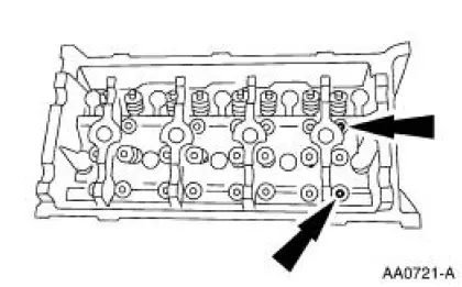
Install the camshafts.
- Lubricate the camshafts with clean engine oil.
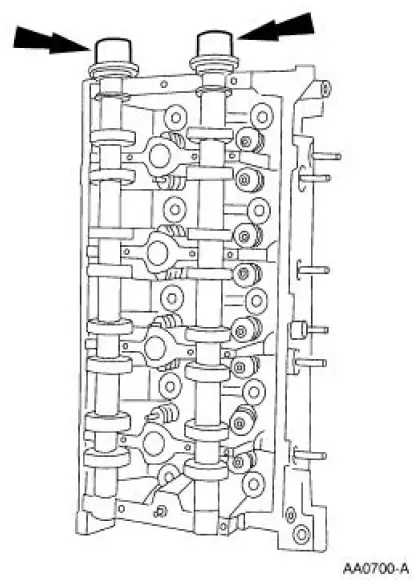
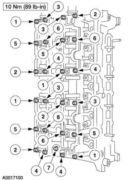
6. Install the camshaft bearing cap assemblies.
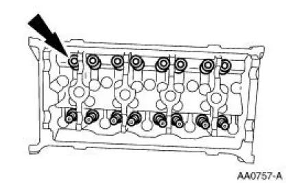
7. Install the hydraulic lash adjusters.
8. Install the roller followers.
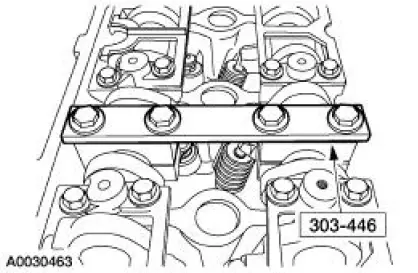
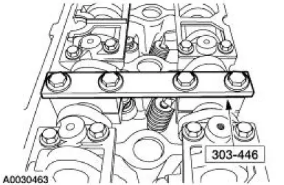
1. Install the special tool on the valve spring.
2. Compress the spring and install the roller follower.
9. Repeat the previous step for the remaining roller followers.
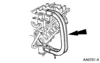
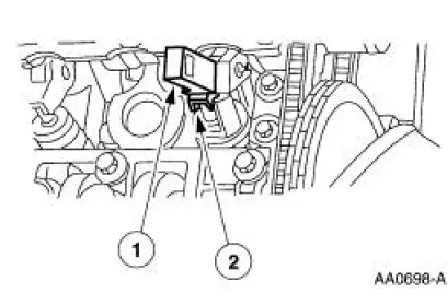
10. NOTE: LH tensioner is shown, RH tensioner is similar.
Install the tensioner.
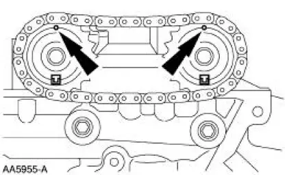
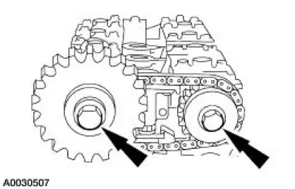
11. CAUTION: Timing marks must be at 12 o'clock and indexed at 6 o'clock.
Install the camshaft sprockets and the chain as an assembly.
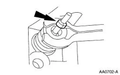
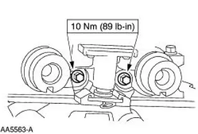
12. Install the special tool.
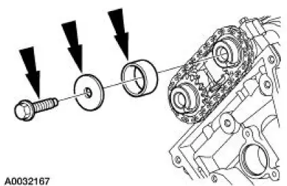
13. Install the camshaft spacer, washer and bolt, and hand-tighten the bolt.
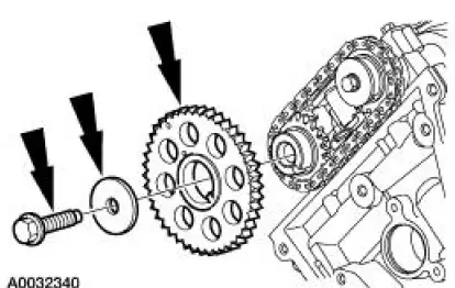
14. Install the camshaft sprocket, washer and bolt, and hand-tighten the bolt.
15. Tighten the bolts in two stages:
- Stage 1: Tighten to 40 Nm (30 lb-ft).
- Stage 2: Tighten and additional 90 degrees.
16. Remove the special tool.
 Disassembly
1. CAUTION: Do not place the cylinder head flat on the bench; the
valves will bend.
CAUTION: Before disassembly begins, mark the valve position on the face of each
valve being removed. The valves mu ...
 Piston - Pin Connecting Rod, Floating Pin
Material
Item
Specification
SAE 5W-20 Premium Synthetic
Blend Engine Oil
XO-5W20-QSP
WSS-M2C153-
H
Disassembly
1. Remove the clips.
2. Remove the piston pin from the piston ...
Other materials:
Cleaning the engine
Engines are more efficient when they are clean because grease and dirt
buildup keep the engine warmer than normal.
When washing:
• Take care when using a power washer to clean the engine. The
high-pressure fluid could penetrate the sealed parts and cause
da ...
Idle Air Control (IAC) Valve - 4.6L (2V)
Removal
1. Disconnect the battery ground cable. For additional information,
refer to Section.
2. NOTE: Discard the idle air control (IAC) valve gasket.
Remove the IAC valve.
Disconnect the connector.
Disconnect the hose.
Remove the bolts, ...
Hose
Special Tool(s)
Installer Set, Teflon Seal
211-D027 (D90P-3517-A) or
equivalent
Removal and Installation
CAUTION: While servicing the power steering system, make sure to plug
all open hoses,
line fittings, and fluid ports to prevent the entr ...
