Ford Mustang (1999-2004) Service Manual: Disassembly
1. CAUTION: Do not place the cylinder head flat on the bench; the valves will bend.
CAUTION: Before disassembly begins, mark the valve position on the face of each valve being removed. The valves must be re-installed into the same positions.
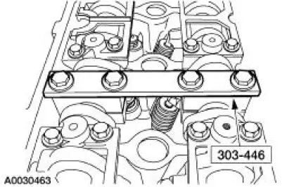
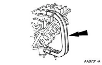
Install the special tool.
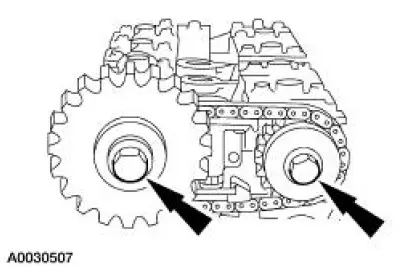
2. Remove the exhaust camshaft sprocket and the intake camshaft bolt, washer and spacer.
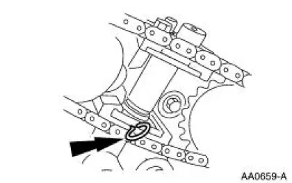
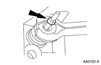
3. Compress the tensioner and install a lock pin.
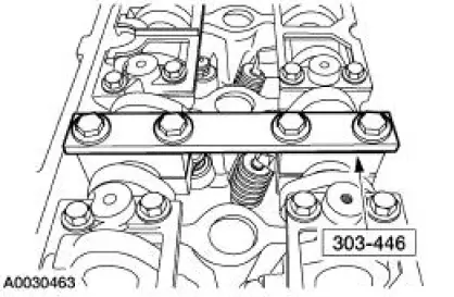
4. Remove the special tool.
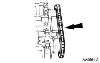
5. Remove the timing chain and the camshaft sprocket.
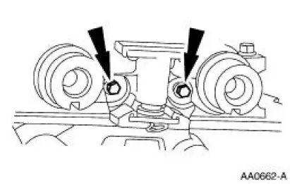
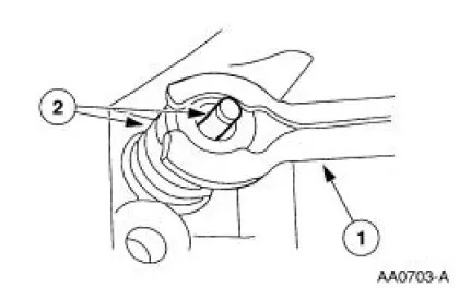
6. NOTE: LH tensioner is shown, RH tensioner is similar.
Remove the tensioner.
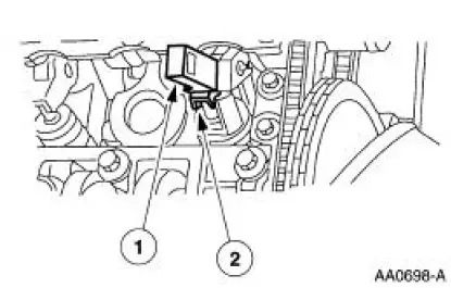
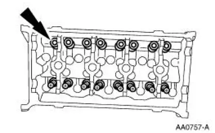
7. Remove the roller followers on the base circle.
1. Install the special tool on the valve spring.
2. Compress the tool and remove the roller follower.
8. Repeat the previous step for the remaining roller followers.
9. Remove the hydraulic lash adjusters.
10. CAUTION: Make sure the tool is seated correctly on the valve spring. Apply a small amount of air at a time. This will prevent the tool from shifting and causing damage to the cylinder head.
Install the air-operated spring compressor on the cylinder head.
11. Compress the valve spring compressor and remove the key from the valves.
12. Remove the intake valves and the valve springs.
1. Release the pressure and remove the valve spring compressor.
2. Remove the intake valves and the valve springs from the cylinder head.
13. Remove the valve stem seals.
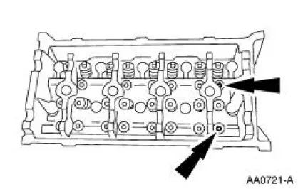
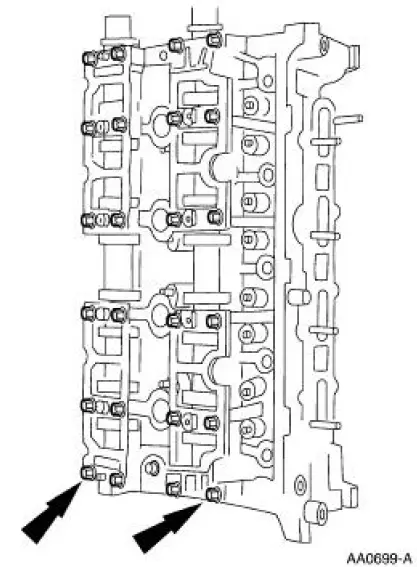
14. CAUTION: The outer bolts on the outer cam bearing cap (exhaust) are longer and must be returned to the same location or engine damage may occur.
NOTE: Identify the camshaft-to-cylinder head location. Caps are not interchangeable.
Remove the bolts and the camshaft bearing cap assemblies.
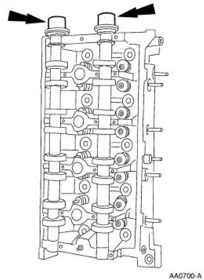
15. Remove the camshafts.
 Cylinder Head
Special Tool(s)
Compressor, Valve Spring
(Exhaust Side)
303-567 (T97P-6565-AH)
Compressor, Valve Spring
(Intake Side)
303-452 (T93P-6565-AR)
Holding Tool, ...
 Assembly
1. Install the valve stem seals.
2. Install the valves and the valve springs.
3. CAUTION: Make sure the tool is seated correctly on the valve spring.
Apply a small
amount of air at a time. This wil ...
Other materials:
Dual-Function Pressure Switch (4.6L)
The dual-function pressure switch is used to interrupt A/C compressor
operation in the event of high system discharge pressures.
The dual-function pressure switch is mounted on a Schrader valve-type
fitting on the high
pressure side of the A/C manifold ...
Wheel Studs
Removal
1. Remove the wheel hub (1104). For additional information, refer to Wheel
Hub and Bearing in
this section.
2. Using a press, remove the wheel stud (1107) from the wheel hub.
Installation
1. Using a press, install a new wheel stud.
2. Install the w ...
Installation
1. NOTE: A new torque converter drain plug must be used.
Install the torque converter drain plug.
2. Install the torque converter housing plug.
3. CAUTION: If installing a new filter, and the seal remains in the
main control bore,
carefully use a small ...
