Ford Mustang (1999-2004) Service Manual: Battery (Diagnosis and Testing)
Special Tool(s)
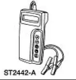 |
Micro 490 Digital Battery Analyzer 162-00004 |
Inspection and Verification
1. Verify the customer concern by operating the system.
2. Visually inspect for obvious signs of mechanical or electrical damage.
Visual Inspection Chart
| Mechanical | Electrical |
|
|
3. If an obvious cause for a concern is found, correct the cause before proceeding to the next step.
4. If the fault is not visually evident, proceed to the pinpoint test.
Pinpoint Tests
PINPOINT TEST A: BATTERY CONDITION TEST
| Test Step | Result / Action to Take |
| A1 TEST BATTERY CONDITION | Yes Does the meter read, GOOD BATTERY? RETURN the battery to service. REFER to Section. Does the meter read, GOODRECHARGE? CHARGE the battery and RETURN to service. REFER to Section. Does the meter read, CHARGE & RETEST? Fully CHARGE the battery and RETEST No Does the meter read, REPLACE BATTERY? INSTALL a new battery. Does the meter read, BAD CELLREPLACE? INSTALL a new battery. |
NOTE: No battery with a red test-eye should be replaced. The red eye only means the battery is discharged, not necessarily defective. NOTE: Failure to fully charge the battery before retesting may cause false readings.
|
 Battery and Cables
Vehicles are equipped with a 12 volt maintenance-free battery that
contains a built-in hydrometer. The
hydrometer eye indication is as follows:
A green dot means the battery is OK.
A yel ...
 Battery Disconnect
WARNING: Batteries normally produce explosive gases which can
cause personal injury.
Therefore, do not allow flames, sparks or lighted substances to come
near the battery, always
shield you ...
Other materials:
Principles of Operation
Battery Saver
The battery saver feature provides automatic shut-off of power to demand
and courtesy lamp circuitry.
When the generic electronic module (GEM) detects the ignition switch
circuits are in the key OFF or
removed ignition key positions, powe ...
Air Conditioning (A/C) System Flushing
Special Tool(s)
A/C Flush and Purge Machine
219-00022 (part of 219-00023)
or equivalent
A/C Flush and Purge Fitting Kit
219-00024 (part of 219-00023)
or equivalent
WARNING: Use extreme care and observe all safety and service
...
Pump - CII
Special Tool(s)
Teflon Seal Replacer Set
211D027 (D90P-3517-A) or
equivalent
Removal and Installation
1. Disconnect the power steering hose. Remove and discard the seal ring.
2. Disconnect the power steering hose.
3. Remove the pulley.
...
