Ford Mustang (1999-2004) Service Manual: Brake Booster - Hydro-Boost (Removal and Installation)
Special Tool(s)
|
|
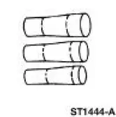
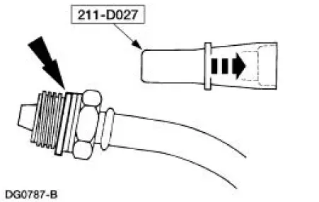
Installer Set, Teflon Seal 211-D027 (D90P-3517-A) or equivalent |
Removal
WARNING: The power brake booster should not be carried by the accumulator, nor should it ever be dropped on the accumulator. Check the snap ring on the accumulator for correct seating before the power brake booster is used. The accumulator contains highpressure nitrogen gas and can be dangerous if mishandled.
WARNING: If the accumulator is to be disposed of, it must not be exposed to excessive heat. Before discarding the accumulator, drill a 1.6-mm (1/16-inch) diameter hole in the end of the accumulator can to relieve the gas pressure. Always wear safety glasses when performing this operation.
1. With the engine off, depress the brake pedal (2455) several times to discharge the accumulator.
2. Disconnect the battery ground cable (14301).
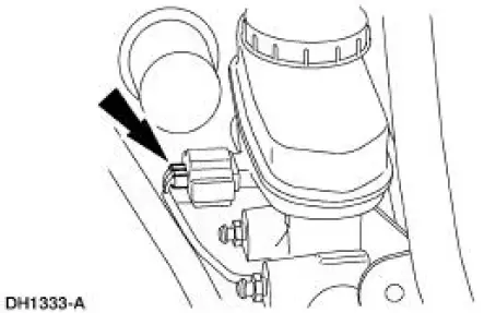
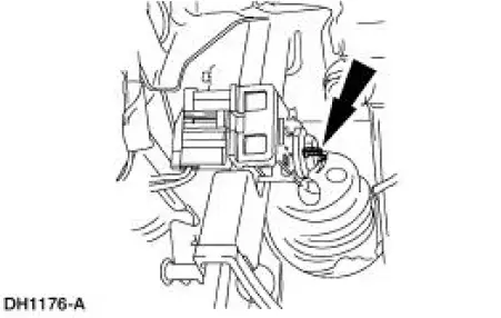
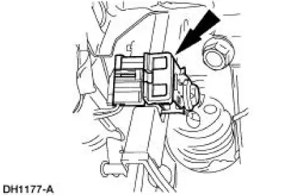
3. Disconnect the fluid level sensor connector.
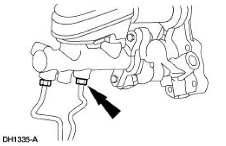
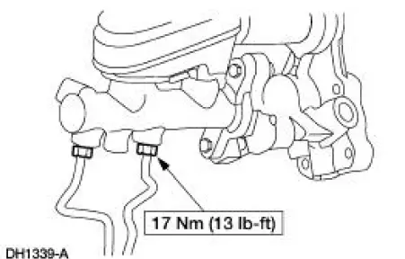
4. Disconnect the brake tubes.
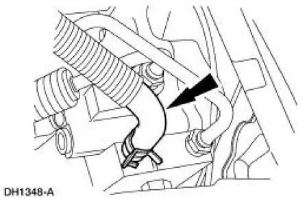
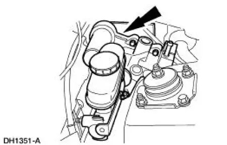
5. Disconnect the power steering return line hose (3A005).
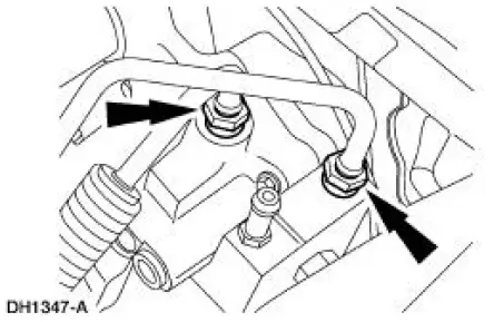
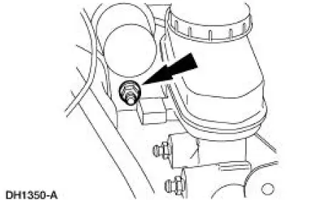
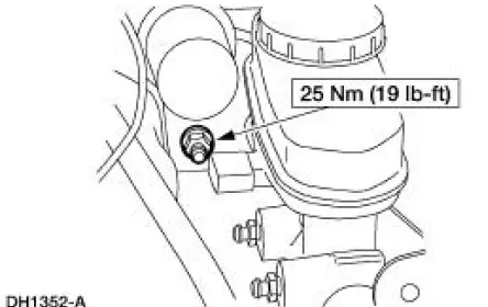
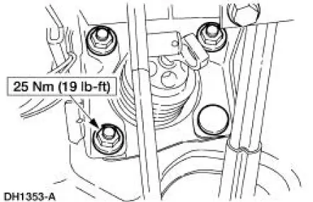
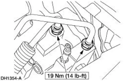
6. Disconnect the power steering pressure lines.
7. Remove the self-locking pin.
8. Remove the stoplight switch (13480) and the brake booster push rod from the brake pedal pin.
9. Remove the power brake booster nuts.
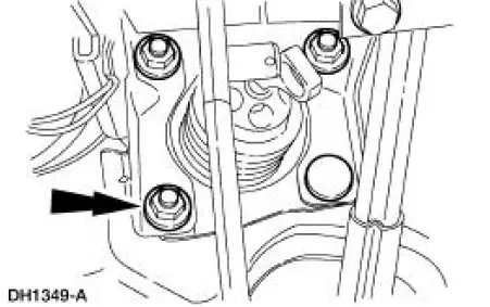
10. Remove the power brake booster nut.
11. Remove the booster.
Installation
1. Follow the removal procedure in reverse order.
- Install new Teflon seals on the power steering pressure fittings.
- Bleed Hydro-Boost. For additional information, refer to Hydro-Boost Bleeding in this section.
- Bleed the brake system.
 Brake Booster - Vacuum (Removal and Installation)
Removal
1. Disconnect the battery ground cable (14301).
2. Remove the air cleaner housing.
3. Remove the brake master cylinder nuts.
4. Position the brake master cylinder (2140) aside.
5. W ...
 Anti-Lock Control - Rear
Torque Specifications
Anti-Lock Control
The four wheel anti-lock brake system (4WABS) consists of the following
components:
anti-lock brake control module (2C346)
front anti-lock brake senso ...
Other materials:
Installation
WARNING: To reduce the risk of serious personal injury, read
and follow all warnings,
cautions and notes at the beginning of the removal procedure.
1. Install the passenger air bag module.
1. Position the passenger air bag module into the instrume ...
Removal
CAUTION: Suspension fasteners are critical parts because they affect
performance of vital
components and systems and their failure can result in major service expense. A
new part with
the same part number must be installed if installation becomes necessary. ...
Sensor Indicator - Rear
Special Tool(s)
Pinion Bearing Cone Remover
205-D002 (D79P-4621A)
Axle Bearing/Seal Plate
205-090 (T75L-1165-B)
Sensing Ring Replacer
206-041 (T89P-20202-A)
Removal
1. Remove the rear axle shaft bearing.
2. Using the special ...
