Ford Mustang (1999-2004) Service Manual: Brake Booster - Vacuum (Removal and Installation)
Removal
1. Disconnect the battery ground cable (14301).
2. Remove the air cleaner housing.
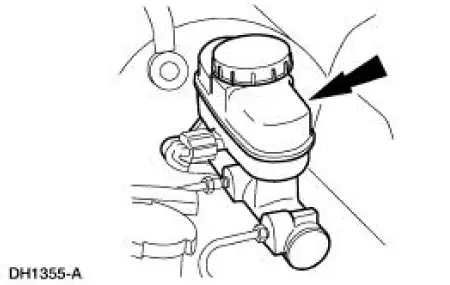
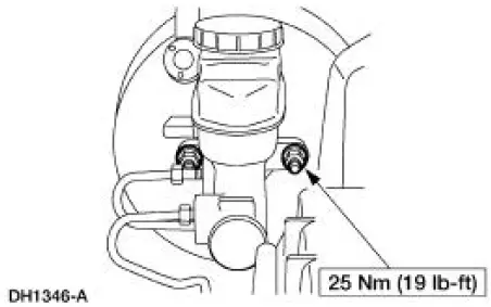
3. Remove the brake master cylinder nuts.
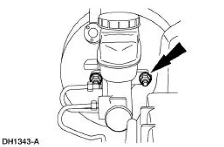
4. Position the brake master cylinder (2140) aside.
5. With the engine off, depress the brake pedal (2455) several times to discharge the accumulator.
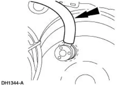
Disconnect the booster vacuum hose.
6. Remove the stoplight switch self-locking pin.
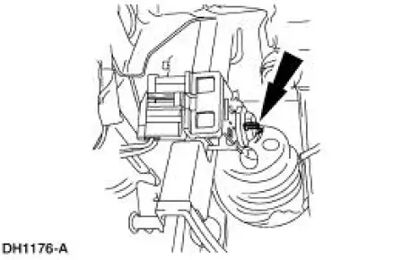
7. Remove the stoplight switch (13480) and the brake booster push rod from the brake pedal pin.
8. Remove the power brake booster nuts.
9. Remove the power brake booster (2005).
Installation
1. Follow the removal procedure in reverse order.
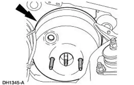
 Hydro-Boost Bleeding
1. NOTE: The Hydro-Boost power brake booster (2B560) is generally
self-bleeding, and the
following procedure will normally bleed the air from the power brake booster.
Normal operation
of the vehicle ...
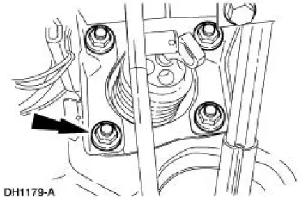
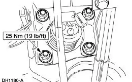
 Brake Booster - Hydro-Boost (Removal and Installation)
Special Tool(s)
Installer Set, Teflon Seal
211-D027 (D90P-3517-A) or
equivalent
Removal
WARNING: The power brake booster should not be carried by the
accumulator, nor
should it e ...
Other materials:
Glass, Frames and Mechanisms (Description and Operation)
Component Location
Windshield Glass
The windshield exterior mouldings are installed with the windshield
glass. The windshield exterior
mouldings cannot be replaced without removal of the windshield.
Window Regulator Control Switch
Power windows ...
Transmission (INSTALLATION)
Special Tool(s)
Retainer, Torque Converter
307-346 (T97T-7902-A)
Material
Item
Specification
Multi-Purpose Grease
D0AZ-19584-AA
ESB-M1C93-
B
MERCON V Automatic
Transmission Fluid
XT-5-QM, XT-5-DM
MERCON V
1. CA ...
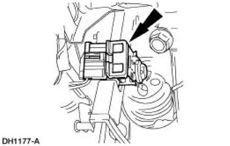
Throttle Position (TP) Sensor
Removal
NOTE: The 3.8L engine is shown; the 4.6L (2V) is similar.
1. Disconnect the battery ground cable. For additional information,
refer to Section.
2. Remove the throttle position (TP) sensor.
Disconnect the connector.
Remove the screws, ...
