Ford Mustang (1999-2004) Service Manual: Brake Booster - Vacuum (Description and Operation)
Power Brake Booster
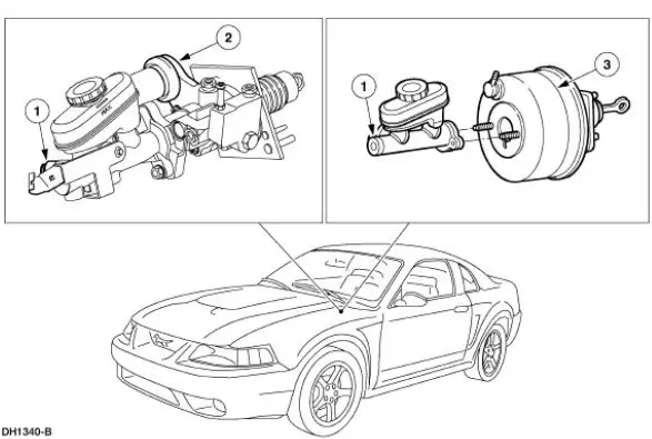
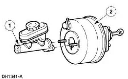
The vacuum type power brake booster (2005):
- is a dual diaphragm, vacuum assisted power brake booster
- reduces brake pedal force and travel distance.
- is located on the LH side of the bulkhead in the engine compartment, between the brake pedal (2455) and the brake master cylinder (2140).
- is divided into separate chambers by the diaphragms.
- will not operate if vacuum is restricted or if any of the vacuum related power brake components fail.
- is installed as an assembly.
If the power assist fails, the brake system will continue to operate with increased brake pedal effort.
Hose and Check Valve
The power brake booster check valve (2365):
- is located on the front of the power brake booster.
- is installed separately; (install a new grommet when installing a new check valve).
- is positioned between the power brake booster and the power brake booster hose.
- closes when the engine is turned off.
- in the closed position, traps engine vacuum in the power brake booster
- retains vacuum to provide several power assisted brake applications with the engine off.
 Power Brake Actuation
Torque Specifications
...
 Brake Booster - Hydro-Boost (Description and Operation)
The Hydro-Boost brake booster is a hydraulically operated brake booster
powered by the power
steering pump (3A674). The power steering pump provides the fluid pressure to
operate both the
power brak ...
Other materials:
Removal
1. Remove the roller followers. For additional information, refer to Roller
Followers in this section.
2. Remove the LH timing chain for the LH side and both timing chains for the RH
side. For
additional information, refer to Timing Drive Components in this ...
Inspection and Verification
1. Verify the customer concern.
2. Visually inspect for obvious signs of mechanical and electrical damage.
Visual Inspection Chart
Mechanical
Electrical
Fuel tank
Engine coolant level
Accessory drive belt
Engine oil level
Par ...
Steering Column Switches
Torque Specifications
Steering Column Switches (DESCRIPTION AND OPERATION)
The steering column switches system consists of the following components:
multifunction switch (13K359)
key release button (manual transmission only) (3F527)
ignition switch (11572 ...
