Ford Mustang (1999-2004) Service Manual: Brake Booster - Hydro-Boost (Description and Operation)
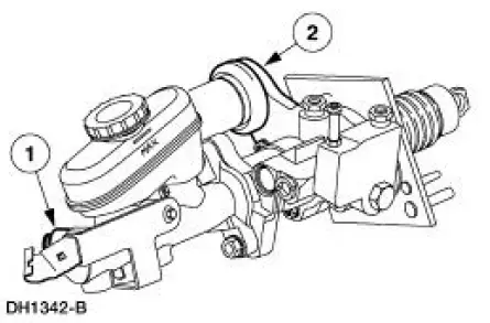
The Hydro-Boost brake booster is a hydraulically operated brake booster powered by the power steering pump (3A674). The power steering pump provides the fluid pressure to operate both the power brake booster and the power steering gear (3504).
A Hydro-Boost reserve system (accumulator) stores sufficient fluid under pressure to provide at least two power-assisted brake applications in the event the power steering pump fluid flow is interrupted.
For low assist concerns on vehicles equipped with the Hydro-Boost system, refer to Section to check the power steering pump pressure and flow.

The brakes can also be applied manually if the reserve system is depleted.
Any leakage goes directly back to the power steering pump reservoir (3E764).
 Brake Booster - Vacuum (Description and Operation)
Power Brake Booster
The vacuum type power brake booster (2005):
is a dual diaphragm, vacuum assisted power brake booster
reduces brake pedal force and travel distance.
is located on ...
 Hydro-Boost Bleeding
1. NOTE: The Hydro-Boost power brake booster (2B560) is generally
self-bleeding, and the
following procedure will normally bleed the air from the power brake booster.
Normal operation
of the vehicle ...
Other materials:
Key Programming - Additional Key With One Programmed
Key
Special Tool(s)
Worldwide Diagnostic System
(WDS)
418-F224,
New Generation STAR (NGS)
Tester
418-F052, or equivalent
diagnostic tool
NOTE: This procedure is used when a customer needs to have an additional key
programmed into the
veh ...
Booster seats
WARNING: Never place, or allow a child to place, the shoulder
belt under a child’s arm or behind the back because it reduces
the protection for the upper part of the body and may increase the risk
of injury or death in a crash.
Use a belt-positioning booster ...
Lifting
CAUTION: Do not allow the lift adapters to contact the steering
linkage, suspension arms,
stabilizer arms, or to compress the lower suspension arm stabilizer bar
insulator (5493).
Damage to the suspension, exhaust and steering linkage components may occur i ...
