Ford Mustang (1999-2004) Service Manual: Brake Shift Interlock Actuator
Removal
1. Remove the shifter top control panel.
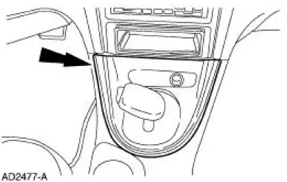
2. Disconnect the electrical connectors.
3. Remove the shifter bezel.
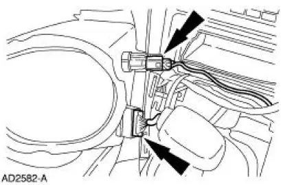
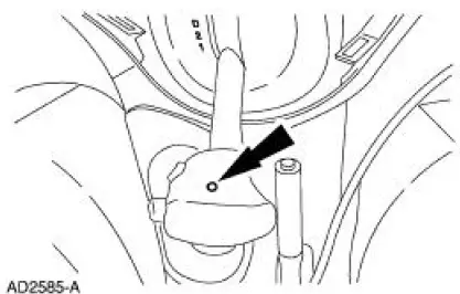
4. Remove the bulb from the bezel.
5. Disconnect the electrical connector.
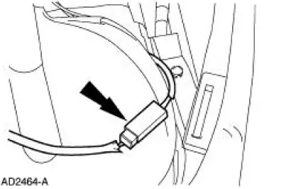
6. CAUTION: Extra force may be needed to lift up on the handle. Do not to pull too far or damage to the overdrive cancel button may result, as the wires may be pulled out of the switch.
Remove the screw and the handle.
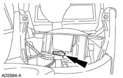
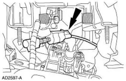
7. Remove the clip and bolt from the brake shift interlock cable.
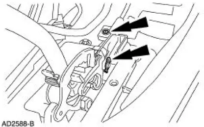
8. Disconnect the shift interlock cable.
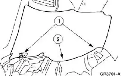
9. Remove the instrument panel steering column cover.
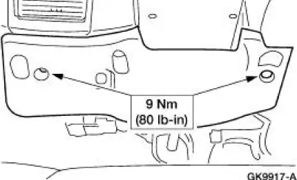
1. Remove the screws.
2. Remove the instrument panel steering column cover.
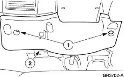
10. Remove the instrument panel reinforcement.
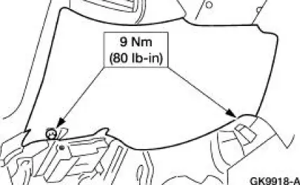
1. Remove the screws.
2. Remove the instrument panel reinforcement.
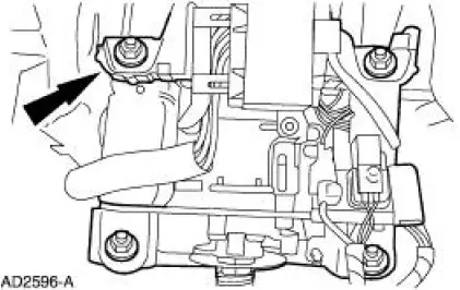
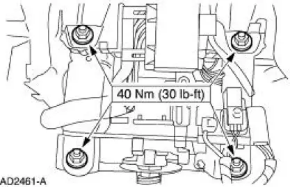
11. Remove the nuts and lower the steering column.
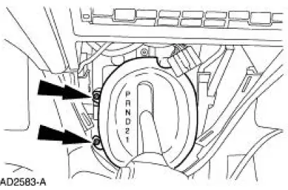
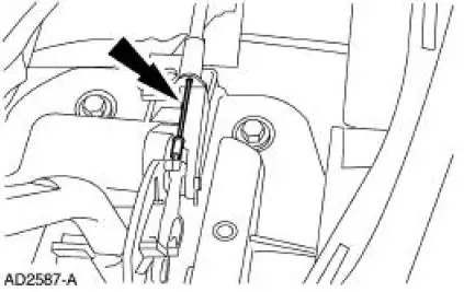
12. Remove the screws from the brake shift interlock cable.
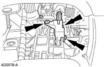
13. Remove the brake shift cable interlock actuator.
Installation
1. To install, reverse the removal procedure.
 Cable Adjustment
1. NOTE: Make sure that the range selector lever is tight
against the rearward overdrive stop.
Place the transmission range selector lever in the overdrive
position.
2. Raise and support the ...
 Cable and Bracket
Removal
1. Raise the vehicle on a hoist. For additional information, refer to
Section.
2. Remove the cable shift from the shifter lever and bracket and discard
the clip.
3. Remove the bol ...
Other materials:
Trim Panel - Upper Quarter
Special Tool(s)
Safety Belt Bolt Bit
501-010 (T77L-2100-A)
Removal and Installation
1. Remove the rear seat cushion.
2. Using the special tool, remove the rear safety belt anchor bolt.
3. Remove the screw and the coat hook.
4. Open the ...
Assembly
1. NOTE: One tab that locks the reverse clutch drum into the reverse
sun shell may be removed.
This is done for balancing purposes.
Inspect the clutch cylinder thrust surfaces, piston bore and clutch plate
serrations for scores or
burrs. Minor scores or bu ...
Towing the vehicle on four whe
Emergency Towing
If your vehicle becomes inoperable (without access to wheel dollies,
car-hauling trailer, or flatbed transport vehicle), it can be flat-towed
(all wheels on the ground, regardless of the powertrain and transmission
configuration) under the fol ...
