Ford Mustang (1999-2004) Service Manual: Installation
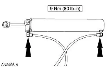
Lift cylinder
1. NOTE: Be sure that each fitting is installed in the correct position on the folding top hydraulic component.
NOTE: Make sure that the tetra seal is installed in the bottom of each of the folding top hydraulic cylinder ports before attaching the upper and lower hose fittings.
Install the hydraulic lines using a thread locker onto the lift cylinder.
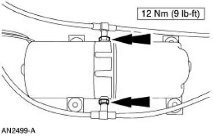
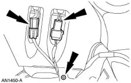
Motor assembly
2. NOTE: Be sure that each fitting is installed in the correct position on the folding top hydraulic component.
Install the hydraulic lines using a thread locker onto the motor assembly.
Hydraulic system
3. Bleed the hydraulic system. For additional information, refer to System Bleeding in this section.
4. Install the motor and cylinders as an assembly.
5. Position the motor assembly.
6. Connect the motor electrical connector.
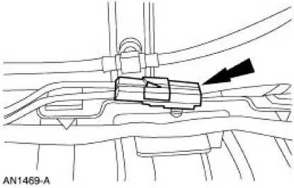
7. Engage the hydraulic line retainers on each side.
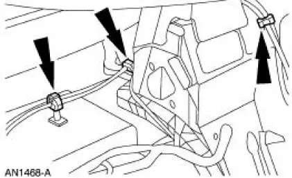
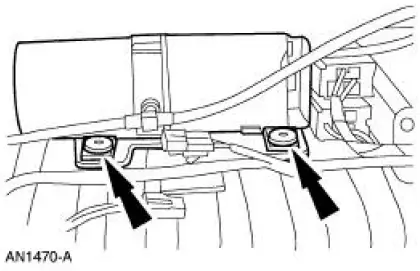
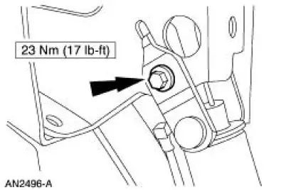
8. Position the lift cylinders and install the nuts.
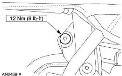
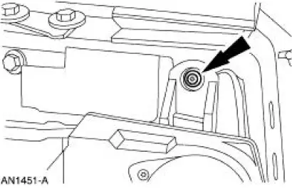
9. Install the two cylinder rod mounting bolts.
10. Install the speakers.
11. Install the screws.
12. NOTE: This step applies to vehicles equipped with the Mach sound system.
Install the screw and connect the electrical connectors.
13. Install the rear quarter trim panel. For additional information, refer to Section.
14. Latch the convertible top.
 Removal
NOTE: The convertible top hydraulic components are removed from the vehicle
as an assembly. The
hydraulic components are individually repaired and the system must be bled
before being installed into ...
 Bumpers
Torque Specifications
Bumpers
CAUTION: Never apply excessive heat to the bumper cover surface. Heat
could cause
distortion of the bumper cover.
The bumper systems consist of the following components ...
Other materials:
Using snow chains
WARNING: Driving too fast for conditions creates the possibility
of loss of vehicle control. Driving at very high speeds for
extended periods of time may result in damage to vehicle components.
WARNING: Snow tires must be the same size, load index, speed
ratin ...
Assembly
1. Using the special tool, install the front pump seal assembly.
2. Install the clutch piston seals.
1. Install the intermediate clutch piston outer seal.
2. Install the intermediate clutch piston inner seal.
3. NOTE: Coat the intermediate clutch pist ...
Steering Column Shaft
Removal and Installation
1. CAUTION: Do not allow the steering column shaft to rotate while
intermediate shaft
is disconnected or damage to the clockspring can result. If there is evidence
that the
steering column shaft has rotated the clockspring must be re ...
