Ford Mustang (1999-2004) Service Manual: Caliper (Disassembly and Assembly)
Special Tool(s)
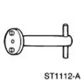 |
Rear Caliper Piston Adjuster 206-026 (T87P-2588-A) |
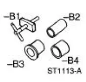 |
Rear Caliper Spring Compressor Set 206-S027 (T87P-2588-B) |
Disassembly
1. Remove the rear disc brake caliper (2552). For additional information, refer to Caliper in the Removal and Installation portion of this section.
2. Drain the brake fluid from the rear disc brake caliper.
3. Secure the rear disc brake caliper in a vise.
4. Turn the rear disc brake piston and adjuster (2B588) counterclockwise with Rear Caliper Piston Adjuster.
5. Remove the rear disc brake piston and adjuster from the caliper bore.
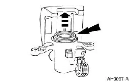
6. Remove and discard the piston dust boot seal and piston seal from the caliper bore.
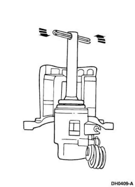
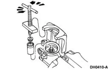
7. CAUTION: The parking brake lever pin retainer clip (2A746) and spring cover are spring-loaded. Use care when removing the parking brake lever pin retainer clip.
Remove the parking brake lever pin retainer clip.
- Unload the spring tension from the parking brake lever pin retainer clip and spring cover using Screw and Cross Block, a 6-mm washer head nut and a 1/2-inch drive 14-mm socket.
- Remove the parking brake lever pin retainer clip with suitable snap-ring pliers.
- Remove Screw and Cross Block.
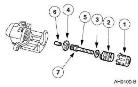
8. Remove the following components:
1. spring cover
2. spring
3. washer
4. key plate
5. push rod
6. strut pin
7. push rod O-ring
9. Remove and discard the O-ring seal from the push rod.
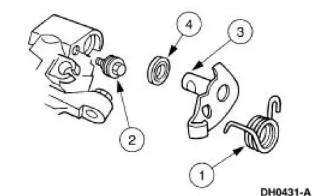
10. Remove the parking brake lever (2A637).
1. Remove the parking brake return spring (2456).
2. Remove the limiting bolt (2A795).
3. Remove the parking brake lever.
4. Remove the parking brake lever shaft seal from the caliper bore.
Assembly
1. CAUTION: Do not reuse piston seals or dust boots. Install new seals or dust boots or damage to the vehicle can occur.
NOTE: Use new brake fluid when assembling and bleeding the brake system.
NOTE: Lightly lubricate the parking brake lever bore, limiting bolt, parking brake lever shaft and parking brake shaft recess with Silicone Dielectric Compound D7AZ-19A331-A or equivalent meeting Ford specification ESE-M1C171-A.
Follow the disassembly procedure in reverse order.
 Shield
Removal
1. Remove the brake disc (2C026). For additional information, refer
to Disc in this section.
2. Remove the brake disc shield bolts.
Installation
1. Follow the removal procedure in r ...
 Parking Brake and Actuation
Torque Specifications
...
Other materials:
General information
Note: Occasional brake noise is normal. If a metal-to-metal,
continuous
grinding or continuous squeal sound is present, the brake linings may be
worn out. Have them inspected by an authorized dealer. If your vehicle
has continuous vibration or shudder in the ...
Door Alignment
NOTE: The door should be adjusted for even and parallel fit with the
body opening and surrounding
panels as well as making sure that the anti-chuck pin is not binding on
convertible models.
1. Mark the position of the front door hinges to the front ...
Reverse Clutch
Special Tool(s)
Dial Indicator Gauge with
Holding Fixture
100-002 (TOOL-4201-C)
Compressor, Clutch Spring
307-015 (T65L-77515-A)
Protector, Transmission
Reverse Clutch Outer Fluid
Seal
307-424
Protecto ...
