Ford Mustang (1999-2004) Service Manual: Rear Subframe
Removal and Installation
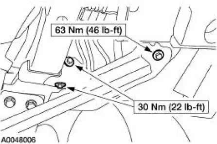
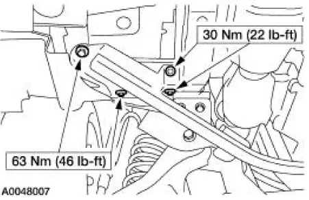
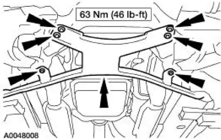
CAUTION: Suspension fasteners are critical parts because they affect performance of vital components and systems and their failure can result in major service expense. A new part with the same part number must be installed if installation becomes necessary. Torque values must be used as specified during reassembly.
1. Remove the rear coil springs. For additional information, refer to Section.
2. Using the special tool, raise the rear subframe.
3. Remove and discard the rear subframe front bolts.
4. Using the special tool, lower and remove the rear subframe.
5. NOTE: Discard the old bolts and nuts. Do not reuse, install new bolts and nuts.
To install, reverse the removal procedure.
Subframe Support -Convertible
Removal and Installation
1. Raise and support the vehicle. For additional information, refer to Section.
2. Support the front subframe support.
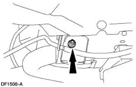
3. Remove the RH front subframe support bolts.
4. Remove the LH front subframe support bolts.
5. Remove the front subframe support.
- Remove the bolts and lower the front subframe support.
6. To install, reverse the removal procedure.
 Front Subframe - 4.6L (4V) Engine
Special Tool(s)
3-Bar Engine Support Kit
303-F072
Lifting Bracket, Engine
303-D088 (D93P-6001-A2)
Removal and Installation
All vehicles
1. Remove the steering gear. For a ...
 General Information
INTRODUCTION
In the past, when cars were simpler, diagrams were simpler. All components
were connected by wires, and
diagrams seldom exceeded 4 pages in length. Today, some wiring diagrams require
m ...
Other materials:
Lumbar Control Switch
Removal and Installation
All vehicles
1. Remove the front seat. For additional information, refer to Seat-Front
Power in this section.
Vehicles with standard power lumbar
2. Pull to remove the lumbar control switch (14C715).
3. Disconnect the power lum ...
Automatic Transaxle/Transmission
General Specifications
a - MERCON V is not interchangeable at this time with the current MERCON
fluids. Check the
transmission fluid level indicator to determine the correct fluid and refer to
the Workshop/Owner
publication to determine the correct service ...
Utilizing the mediation or arbitration program
(Canada only)
This pertains to vehicles delivered to authorized Canadian dealers.
In those cases, where you continue to feel that the efforts by Ford of
Canada and the authorized dealer to resolve a factory-related vehicle
service concern have been unsatisfactory, Ford of ...
