Ford Mustang (1999-2004) Service Manual: Keyless Entry (Diagnosis and Testing)
Refer to Wiring Diagrams Cell 59 , Generic Electronic Module for schematic and connector information.
Refer to Wiring Diagrams Cell 111 , Remote Keyless Entry (RKE) for schematic and connector information.
Special Tool(s)
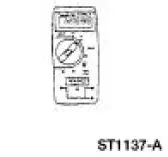 |
73 Digital Multimeter or equivalent 105-R0051 |
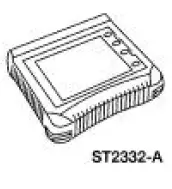 |
Worldwide Diagnostic System (WDS) 418-F224 New Generation STAR (NGS) Tester 418-F052, or equivalent scan tool |
 Switch - Door Lock
Removal
1. CAUTION: Place a rag between the window regulator switch
plate and the door trim
panel to avoid damaging the door trim panel.
Position the window regulator switch plate (14524) asi ...
 Principles of Operation
NOTE: Battery power and ground must be remove before disconnecting
the GEM connectors to avoid
setting false codes.
Power Locks Operation
The power locks feature allows the customer to lock a ...
Other materials:
Catalyst Monitor Sensor
Special Tool(s)
Socket, Exhaust Gas Oxygen
Sensor
303-476 (T94P-9472-A)
Material
Item
Specification
Penetrating and Lock Lubricant
or equivalent
E8AZ-19A501-
B
Removal and Installation
1. Disconnect the battery ground ...
Pinpoint Test F: LFC 16/DTC B1888 - Passenger Air Bag Circuit Shorted to
Ground
Normal Operation
The restraints control module (RCM) checks for passenger air bag circuit
shorts to ground by
monitoring the voltage of circuits 607 (LB/OG) and 616 (PK/BK) at pins 6 and
7. If the RCM detects a
short to ground on either of these pins, i ...
Adjusting the headlamps
The headlamps on your vehicle are properly aimed at the assembly plant.
If your vehicle has been in an accident, an authorized dealer should
check the alignment of your headlamps.
Vertical Aim Adjustment
1. Park the vehicle directly in front of a wall or scre ...
