Ford Mustang (1999-2004) Service Manual: Diagnostics
Special Tool(s)
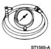 |
Transmission Fluid Pressure Gauge 307-004 (T57L-77820-A) |
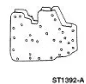 |
Air Test Plate, Transmission 307-246 (T92P-7006-A) |
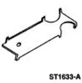 |
Alignment Gauge, TR Sensor 307-351 (T97L-70010-A) |
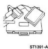 |
Breakout Box, EEC-V Control System 418-049 (T94L-50-EEC-V) or equivalent |
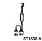 |
MLP-TR Cable 418-F107 (007-00111) or equivalent |
 |
Worldwide Diagnostic System (WDS) 418-F224 New Generation STAR (NGS) Tester 418-F052 or equivalent scan tool |
 |
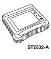
Transmission Tester 307-F016 (007-00130) or equivalent |
 |
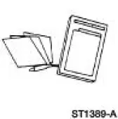
Trans Tester TR/MLP Overlay and Manual 007-00131 or equivalent |
 |
73 III Automotive Meter 105-R0057 or equivalent |
 |
UV Leak Detector Kit 164-R0756 or equivalent |
Diagnosing an electronically controlled automatic transmission is simplified by using the following procedures. One of the most important things to remember is that there is a definite procedure to follow. DO NOT TAKE SHORT CUTS OR ASSUME THAT CRITICAL CHECKS OR ADJUSTMENTS HAVE ALREADY BEEN MADE. Follow the procedures as written to avoid missing critical components or steps. By following the diagnostic sequence, the technician will be able to diagnose and repair the concern the first time.
On-Board Diagnostics With Diagnostic Tool
NOTE: For detailed instruction and other diagnostic methods using the scan tool, refer to the scan tool tester manual and the Powertrain Control/Emissions Diagnosis (PC/ED) manual. These quick tests should be used to diagnose the powertrain control module (PCM) and should be carried out in order.
- Quick Test 1.0 - Visual Inspection
- Quick Test 2.0 - Set Up
- Quick Test 3.0 - Key On, Engine Off (KOEO)
- Quick Test 4.0 - Continuous Memory
- Quick Test 5.0 - Key On, Engine Running (KOER)
- Special Test Mode
- Wiggle Test
- Output Test Mode
- PCM Reset Mode
- Clearing DTCs
- OBD II Drive Cycle
- Other Scan Tool Features
For further information on other diagnostic testing features using the scan tool, refer to the Powertrain Control/Emissions Diagnosis (PC/ED) manual. Other diagnostic methods include the following:
- Parameter Identification (PID) Access Mode
- Freeze Frame Data Access Mode
- Oxygen Sensor Monitor Mode
 Torque Converter Diagnosis
Prior to the installation of a new or remanufactured torque
converter, all diagnostic procedures must be
followed. This is to prevent the unnecessary installation of torque
converters. Only af ...
 Output State Control (OSC) Mode
Output State Control (OSC) allows the technician to take control of
certain parameters to function the
transmission. For example, OSC allows the technician to shift the
transmission only when ...
Other materials:
Instrument lighting dimmer
• Move the control up or down to
adjust the intensity of the panel
lighting.
• Move the control to the full
upright position, past detent,
to turn on the interior lamps.
• Move the control down, past
detent, to turn off the interior
lights.
Note: The pa ...
Universal Garage Door Opener (If Equipped)
UNIVERSAL GARAGE DOOR OPENER
The appearance of your vehicle’s universal garage door opener will
vary according to your option package. Before programing, make sure
you identify which transmitter you have by comparing it to the graphics
below.
HomeLink®
Ca ...
Tire care
Information About Uniform Tire Quality Grading
Tire Quality Grades apply to new
pneumatic passenger car tires. The Tire
Quality Grades can be found where
applicable on the tire sidewall between
tread shoulder and maximum section
width. For example:
• Treadw ...
