Ford Mustang (1999-2004) Service Manual: Output State Control (OSC) Mode
Output State Control (OSC) allows the technician to take control of certain parameters to function the transmission. For example, OSC allows the technician to shift the transmission only when he/she commands a gear change. If the technician commands 1st gear in OSC, the transmission will remain in 1st gear until the technician commands the next gear. Another example, the technician can command a shift solenoid to turn on or off when carrying out an electrical circuit check. OSC has two modes of operation for transmission, the BENCH MODE and the DRIVE MODE. Each mode/parameter has a unique set of vehicle operating requirements that the technician is required to meet before being allowed to operate OSC.
NOTE: To operate OSC the digital transmission range (TR) sensor must be operational. No Diagnostic Trouble Codes (DTCs) related to the digital TR sensor can be present.
To operate OSC the vehicle speed source must be operational. No diagnostic codes (DTCs) related to this source can be present. The vehicle speed source can vary depending on vehicle configuration.
Technicians should verify which input source is applicable for their vehicle application. The following are potential vehicle speed sources:
- anti-lock braking system (ABS)
- output shaft speed (OSS) sensor
- vehicle speed sensor
- The vehicle requirements MUST BE MET when SENDING the OSC value. Refer to individual test modes for vehicle requirements.
- If the vehicle requirements are NOT MET when SENDING the OSC value, an ERROR MESSAGE will appear. When the ERROR MESSAGE is received, OSC is aborted and must be restarted.
- If AFTER SENDING an OSC value, and the vehicle requirements are no longer met, the PCM will cancel the OSC value and NO ERROR message will appear. Once the vehicle requirements are met again, the PCM will automatically SEND the previous OSC value without any additional actions required by the service technician.
- The OSC value XXX may be sent anytime to cancel OSC.
Output State Control (OSC) Procedures
- Carry out visual inspection and vehicle preparation as required.
- Select "Vehicle and Engine Selection" menu.
- Select appropriate vehicle and engine.
- Select "Diagnostic Data Link."
- Select "Powertrain Control Module."
- Select "Output Test Mode."
- Select "KOEO On-Demand Self Test and KOER On-Demand Self Tests."
- Carry out test and record DTCs.
- Repair all NON-Transmission DTCs.
- Repair all digital TR Sensor DTCs.
- Repair all vehicle speed DTCs.
- Make sure that the vehicle speed sensor and digital TR sensors are functional.
- Select "Active Command Modes."
- Select "Trans - Bench Mode or Trans - Drive Mode."
OSC - Transmission Bench Modes
The following Transmission Bench Modes may be used or required during diagnostics.
SSA, SSB and TCC in BENCH MODE
The BENCH MODE allows the technician to carry out electrical circuit checks on the following components:
- SSA - activates SSA OFF or ON.
- SSB - activates SSB OFF or ON.
- Transmission converter clutch (TCC) - activates TCC OFF or ON.
OSC "SSA, SSB, TCC" BENCH MODE operates ONLY when:
- the digital TR sensor is operational and no digital TR sensor DTCs are present.
- the vehicle speed input is operational and no VSS sensor DTCs are present.
- the transmission range selector lever is in P.
- the key is ON.
- the engine is OFF.
OSC Command Values
- OFF - turns solenoid OFF.
- ON - turns solenoid ON.
- XXX - cancels OSC value sent.
- SEND - sends the values to PCM.
BENCH MODE Procedure for SSA, SSB and TCC
Follow operating instructions from the scan tool menu screen:
- Select "Output State Control."
- Select "Trans - Bench Mode."
- Select "PIDs" to be monitored.
- Monitor all selected PIDs during test.
- Select "Parameters - SSA, SSB or TCC."
- Select "ON" to turn solenoid ON.
- Press "SEND" to send command ON.
- Select "OFF" to turn solenoid OFF.
- Press "SEND" to send command OFF.
- Select "XXX" to cancel at any time.
- Press "SEND."
EPC in BENCH MODE
The BENCH MODE is also used to test the functionality of the transmission's electronic pressure control. During BENCH MODE, the electronic pressure control (EPC) solenoid can ramp up/down in increments of 103 kPa (15 psi) from zero to 620 kPa (90 psi) and 620 kPa (90 psi) to zero psi.
The OSC functions for the parameter EPC allows the technician to choose the following options:
- EPC - activates EPC to selected values.
- 00 - sets EPC pressure to 00 kPa (00 psi).
- 15 - sets EPC pressure to 103 kPa (15 psi).
- 30 - sets EPC pressure to 206 kPa (30 psi).
- 45 - sets EPC pressure to 310 kPa (45 psi).
- 60 - sets EPC pressure to 411 kPa (60 psi).
- 75 - sets EPC pressure to 517 kPa (75 psi).
- 90 - sets EPC pressure to 620 kPa (90 psi).
To carry out an EPC BENCH MODE pressure functionality test, install a pressure gauge in the EPC port. The following requirements are required to carry out this test:
- VSS and digital TR sensor operational
- No VSS and digital TR sensor DTCs
- Transmission range selector lever in P
- Key ON
- Engine ON
- Engine speed at least 1,500 rpm for accurate EPC pressure measurement
To carry out an EPC BENCH MODE solenoid circuit pinpoint test, the following requirements are required.
- VSS and digital TR sensor operational
- No VSS and digital TR sensor DTCs
- Transmission range selector lever in P
- Key ON
- Engine OFF
OSC Command Values
- 00 - sets EPC pressure to 00 kPa (00 psi).
- 15 - sets EPC pressure to 103 kPa (15 psi).
- 30 - sets EPC pressure to 206 kPa (30 psi).
- 45 - sets EPC pressure to 310 kPa (45 psi).
- 60 - sets EPC pressure to 411 kPa (60 psi).
- 75 - sets EPC pressure to 517 kPa (75 psi).
- 90 - sets EPC pressure to 620 kPa (90 psi).
- XXX - cancels OSC value sent.
- SEND - sends the values to PCM.
BENCH MODE Procedure for EPC
Follow operating instructions from the scan tool menu screen:
- Select "Output State Control."
- Select "Trans - Bench Mode."
- Select "PIDs" to be monitored.
- Monitor all selected PIDs during test.
- Select "Parameters - EPC."
- Select Value "0-620 kPa (0-90 psi)."
- Press "SEND" to send command.
- Select "XXX" to cancel at any time.
- Press "SEND."
OSC - Transmission DRIVE MODES
The DRIVE MODE allows control of three transmission parameters. Each mode/parameter has a unique set of vehicle operating requirements that the technician is required to meet before being allowed to operate OSC. The recommended procedure, when using the DRIVE MODE, is to control one parameter at a time.
The DRIVE MODE allows the technician to carry out the following functions on the transmission:
- GR_CM - allows upshifts or downshifts.
- TCC - engages or disengages the torque converter clutch.
- EPC - increases/decreases EPC pressure.
GR_CM in DRIVE MODE
This OSC function is used to test the transmission shift functions.
The OSC functions for the GR_CM parameter allows the technician to choose the following options:
- 1 - PCM selects 1st gear.
- 2 - PCM selects 2nd gear.
- 3 - PCM selects 3rd gear.
- 4 - PCM selects 4th gear.
OSC "GR_CM" Mode operates ONLY when:
- the digital TR sensor is operational and no digital TR sensor DTCs are present.
- the vehicle speed sensor is operational and no VSS sensor DTCs are present.
- the engine is ON.
- the TCC is OFF.
- the transmission range selector lever is in O/D.
- the vehicle speed is greater than 3.2 km/h (2 mph).
OSC Command Values
- 1 - PCM selects 1st gear.
- 2 - PCM selects 2nd gear.
- 3 - PCM selects 3rd gear.
- 4 - PCM selects 4th gear.
- XXX - cancels OSC value sent.
- SEND - sends the values to PCM.
DRIVE MODE Procedure for GR_CM
Follow operating instructions from the scan tool menu screen.
- Select "Output State Control."
- Select "Trans - DRIVE MODE."
- Select "PIDs" to be monitored.
- Monitor all selected PIDs during test.
- Select "Parameters - GR_CM."
- Select Value "1-4."
- Press "SEND" to send command.
- Re-Select Value "1-4."
- Press "SEND" to send command.
- Select "XXX" to cancel at any time.
- Press "SEND."
TCC in DRIVE MODE
This OSC function is used to test whether the torque converter clutch is engaging and disengaging correctly.
The OSC functions for the TCC parameter allows the technician to choose the following:
- TCC - activates TCC OFF and ON.
- ON - turns TCC solenoid ON.
- OFF - turns TCC solenoid OFF.
OSC "TCC OFF" DRIVE MODE operates ONLY when:
- the digital TR sensor is operational and no digital TR sensor DTCs are present.
- the vehicle speed sensor is operational and no VSS sensor DTCs are present.
- the engine is ON.
- the transmission range selector lever is in O/D.
- the vehicle speed is greater than 3.2 km/h (2 mph).
OSC "TCC ON" DRIVE MODE operates ONLY when:
- the digital TR sensor is operational and no digital TR sensor DTCs are present.
- the vehicle speed sensor is operational and no VSS sensor DTCs are present.
- the engine is ON.
- the transmission range selector lever is in O/D.
- the vehicle speed is greater than 3.2 km/h (2 mph).
- the transmission is in 2nd gear or higher.
- the TFT is between 15 and 135C (60 and 275F).
- the brake is not applied "OFF" below 32 km/h (20 mph).
- (Not an excessive load on engine (engine lugging).
OSC Command Values
- OFF - turns TCC OFF.
- ON - turns TCC ON.
- XXX - cancels OSC value sent.
- SEND - sends the values to PCM.
Drive Mode Procedures for TCC
Follow operating instructions from the scan tool menu screen.
- Select "Output State Control."
- Select "Trans - Drive Mode."
- Select "PIDs" to be monitored.
- Monitor all selected PIDs during test.
- Select "Parameters - TCC."
- Select "ON" to turn solenoid ON.
- Press "SEND" to send command ON.
- Select "OFF" to turn solenoid OFF.
- Press "SEND" to send command OFF.
- Select "XXX" to cancel at any time.
- Press "SEND."
EPC in DRIVE MODE
This OSC function is used to increase the EPC pressure while testing the transmission shift functions.
This OSC function can only increase the EPC pressure greater than what the PCM normally commands. If an OSC value, such as (75) or (90) psi is sent, the upshifts and downshifts should exhibit a firmer shift. Firmer shifts would indicate that the EPC pressure control is working at higher pressures. The best test for the EPC is to use the BENCH MODE and a hydraulic pressure gauge.
Using EPC in the BENCH MODE will confirm that the EPC is working at both the higher and lower pressures.
The OSC functions for the parameter EPC allows the technician to choose the following options:
- EPC - activates EPC to selected values
- 00 - sets EPC pressure to 00 kPa (00 psi).
- 15 - sets EPC pressure to 103 kPa (15 psi).
- 30 - sets EPC pressure to 206 kPa (30 psi).
- 45 - sets EPC pressure to 310 kPa (45 psi).
- 60 - sets EPC pressure to 411 kPa (60 psi).
- 75 - sets EPC pressure to 517 kPa (75 psi).
- 90 - sets EPC pressure to 620 kPa (90 psi).
OSC "EPC" DRIVE MODE operates ONLY when:
- the digital TR sensor is operational and no digital TR sensor DTCs are present.
- the vehicle speed sensor is operational and no VSS sensor DTCs are present.
- the transmission range selector lever is in O/D.
- the pressure gauge is installed.
- the key is ON.
- the engine is ON.
- the vehicle speed is greater than 3.2 km/h (2 mph).
- the OSC value for EPC must be greater than what the PCM commands (see EPC PID).
OSC Command Values
- 00 - sets EPC pressure to 00 kPa (00 psi).
- 15 - sets EPC pressure to 103 kPa (15 psi).
- 30 - sets EPC pressure to 206 kPa (30 psi).
- 45 - sets EPC pressure to 310 kPa (45 psi).
- 60 - sets EPC pressure to 411 kPa (60 psi).
- 75 - sets EPC pressure to 517 kPa (75 psi).
- 90 - sets EPC pressure to 620 kPa (90 psi).
- XXX - cancels OSC value sent.
- SEND - sends the values to PCM.
DRIVE MODE Procedure for EPC.
Follow operating instructions from the scan tool menu screen.
- Select "Output State Control."
- Select "Trans - Drive Mode."
- Select "PIDs" to be monitored.
- Monitor all selected PIDs during test.
- Select "Parameters - EPC."
- Select Value "0-620 kPa (0-90 psi)."
- Press "SEND" to send command.
- Re-Select Value "0-620 kPa (0-90 psi)."
- Press "SEND" to send command.
- Select "XXX" to cancel at any time.
- Press "SEND."
Using Output State Control and Accessing PIDs
To confirm that the OSC value was sent by the scan tool and the EEC has accepted the OSC substitution, a corresponding PID for each OSC parameter must be monitored. Additional PIDs should be monitored to help the technician adequately diagnose the transmission.
The following is a list of OSC parameters and their corresponding PID:
OSC PARAMETER CHART
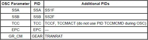
To confirm that the OSC substitution occurred, SEND the OSC value and monitor the corresponding PID value. If no ERROR MESSAGE was received and the value of the corresponding PID remains the same as the value sent from OSC, then the OSC substitution was successful.
 Diagnostics
Special Tool(s)
Transmission Fluid Pressure
Gauge
307-004 (T57L-77820-A)
Air Test Plate, Transmission
307-246 (T92P-7006-A)
Alignment Gauge, TR Sensor
307-35 ...
 Transmission Drive Cycle Test
NOTE: Always drive the vehicle in a safe manner according to driving
conditions and obey all traffic
laws.
NOTE: The Transmission Drive Cycle Test must be followed exactly.
Malfunctions must occur ...
Other materials:
Removal
1. Disconnect the battery ground cable. For additional information, refer
to Section.
2. Remove the engine air cleaner outlet pipe. For additional information,
refer to Section.
3. Disconnect the vacuum hose and the idle air control (IAC) valve
elect ...
Compressor to Condenser Discharge Line - 4.6L
Material
Item
Specification
PAG Refrigerant Compressor
Oil (R-134a Systems)
F7AZ-19589-DA (Motorcraft YN-
12-C)
WSH-M1C231-
B
Removal and Installation
NOTE: Installation of a new suction accumulator is not required when
repairing the ...
Supercharger Cooling (Diagnosis and Testing)
Special Tool(s)
Pressure Test Kit
014-R1072 or equivalent
Battery/Antifreeze Tester
014-R1060 or equivalent
Material
Item
Specification
Motorcraft Premium
Engine Coolant
VC-4-A (in Oregon
VC-5, in Canada
C ...
