Ford Mustang (1999-2004) Service Manual: Digital Transmission Range (TR) Sensor
Special Tool(s)
|
|
Alignment Gauge, TR Sensor 307-351 (T97L-70010-A) |
Removal
1. Disconnect the battery ground cable. For additional information, refer to Section.
2. Raise and support the vehicle. For additional information, refer to Section.
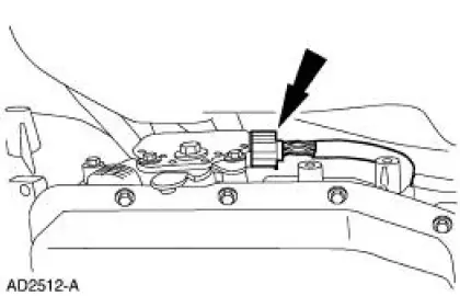
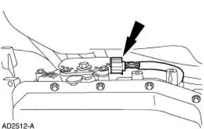
3. Disconnect the connector.
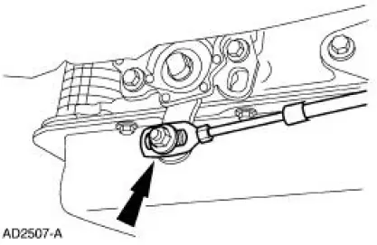
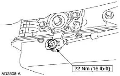
4. Disconnect the manual lever shift control cable.
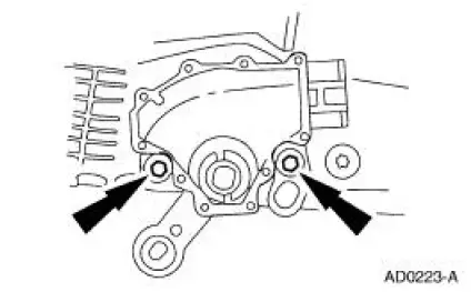
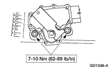
5. Remove the digital TR bolts and the TR sensor.

Installation
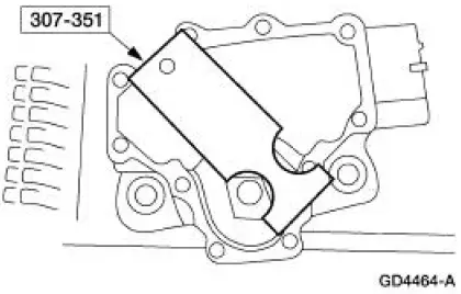
1. Install the digital TR sensor and loosely install the bolts.
2. NOTE: The tool is designed to fit snugly.
NOTE: Manual shift lever shaft must be in the neutral position.
Using the special tool, align the digital TR sensor slots.
3. Tighten the bolts.
4. With the manual lever in overdrive connect the shift lever control cable.
5. Install the digital TR sensor electrical connector.
6. Lower the vehicle.
7. NOTE: When the battery is disconnected and reconnected, some abnormal driving symptoms may occur while the vehicle relearns its adaptive strategy. The vehicle may need to be driven 16 km (10 miles) or more to relearn the strategy.
Connect the battery ground cable.
 Manual Control Lever Shaft and Seal
Special Tool(s)
Installer, Shift Shaft Fluid Seal
307-050 (T74P-77498-A)
Alignment Gauge, TR Sensor
307-351 (T97L-70010-A)
Removal
1. Drain the transmission fluid and re ...
 Reverse Servo Assembly
Special Tool(s)
Dial Indicator Gauge with
Holding Fixture
100-002 (TOOL-4201-C)
Remover/Installer, Servo
Piston
307-251 (T92P-70023-A)
Installer, Servo Pisto ...
Other materials:
Air Conditioning (A/C) Pressure Relief Valve - 3.8L
Material
Item
Specification
PAG Refrigerant Compressor
Oil (R-134a Systems)
F7AZ-19589-DA (Motorcraft YN-
12-C)
WSH-M1C231-
B
Removal and Installation
1. Recover the refrigerant. For additional information, refer to Section.
2. Unlat ...
Accessory Drive Belt - 4.6L (2V) and (4V)
Removal and Installation
Mach I
1. Remove the air intake scoop. For additional information, refer to Section.
Cobra
2. Remove the supercharger drive belt cover.
3. Rotate the supercharger belt tensioner clockwise and remove the
supercharger belt.
4. Remov ...
Camshaft End Play - OHC Engines
Special Tool(s)
Dial Indicator Gauge with
Holding Fixture
100-002 (TOOL-4201-C) or
equivalent
1. Remove the roller followers. Refer to the appropriate section in Group 303
for the procedure.
2. Use a Dial Indicator Gauge with Holding Fixt ...
