Ford Mustang (1999-2004) Service Manual: Dual-Function Pressure Switch (4.6L)
The dual-function pressure switch is used to interrupt A/C compressor operation in the event of high system discharge pressures.
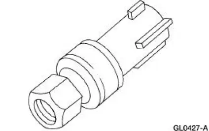
- The dual-function pressure switch is mounted on a Schrader valve-type fitting on the high pressure side of the A/C manifold and tube.
- It is not necessary to discharge the refrigerant system to remove the dual-function pressure switch.
- A valve depressor, located inside the threaded end of the dual-function pressure switch, presses on the Schrader valve stem.
- This allows the dual-function pressure switch to monitor the compressor discharge pressure.
- When the compressor discharge pressure rises, the switch contacts open, disengaging the A/C compressor. When the pressure drops, the contacts close to allow operation of the A/C compressor. For specifications regarding operating pressure(s), refer to Section.
The dual-function pressure switch has a second set of electrical contacts used for high-speed cooling fan control.
When the compressor discharge pressure rises, the contacts close and engage the high speed fan control. When the pressure drops, the contacts open and the high speed fan control is disengaged.
Refrigerant Containment Switch (3.8L)
The refrigerant containment switch is used to interrupt A/C compressor operation in the event of high system discharge pressures.
- The refrigerant containment switch is mounted on a Schrader-type valve fitting on the high pressure side of the compressor manifold and tube assembly.
- A valve depressor, located inside the threaded end of the refrigerant containment switch, presses on the Schrader valve stem.
- This allows the refrigerant containment switch to monitor the A/C compressor discharge pressure.
- When the A/C compressor discharge pressure rises, the switch contacts open, disengaging the A/C compressor. When the pressure drops, the contacts close to allow operation of the A/C compressor. For additional information regarding operating pressure(s), refer to Section.
- It is not necessary to discharge the refrigerant system to remove the refrigerant containment switch.
 Suction Accumulator
NOTE: Installation of a new suction accumulator is not required when
repairing the air conditioning
system except when there is physical evidence of contamination from a failed A/C
compres ...
 Spring Lock Coupling
The spring lock coupling is a refrigerant line coupling held together by a
garter spring inside a circular
cage.
When the coupling is connected together, the flared end of the female
f ...
Other materials:
Evaporative Emission System Leak Test
Special Tool(s)
Evaporative Emission System
Tester 310-F007
(134-00056) or equivalent
Worldwide Diagnostic System
(WDS)
418-F224,
New Generation STAR (NGS)
Tester
418-F052, or equivalent scan
tool
CAUTION: The evaporat ...
Heating and Defrosting
The heating and defrosting system has the following features:
Controls the temperature and, during A/C operation, reduces the relative
humidity of the air
inside the vehicle.
Delivers heated or cooled air to maintain the vehicle interior
temperature an ...
Towing the vehicle on four whe
Emergency Towing
If your vehicle becomes inoperable (without access to wheel dollies,
car-hauling trailer, or flatbed transport vehicle), it can be flat-towed
(all wheels on the ground, regardless of the powertrain and transmission
configuration) under the fol ...
