Ford Mustang (1999-2004) Service Manual: Disassembly
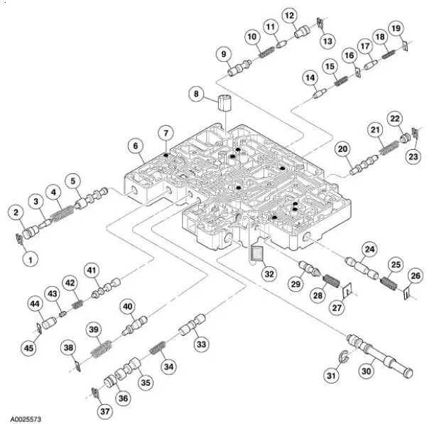
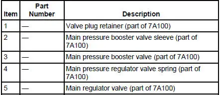
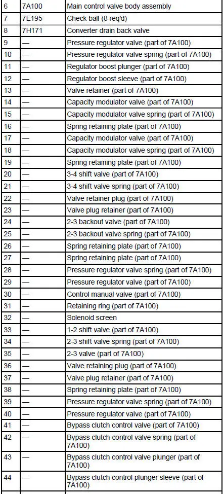
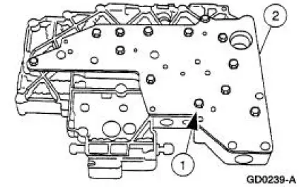
Main Control Valve Body - Disassembled View

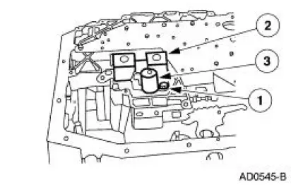
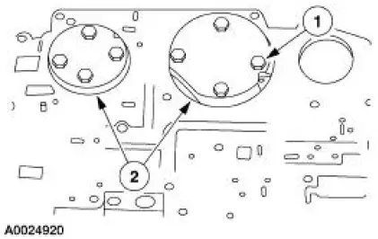
1. Remove the torque converter clutch (TCC) solenoid and the shift solenoid.
1. Remove the bolt.
2. Remove the shift solenoid.
3. Remove the TCC solenoid.
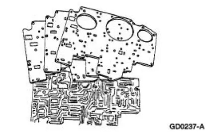
2. Remove the two reinforcement plates.
1. Remove the bolts.
2. Remove the plates.
3. Remove the separator plate and discard the gaskets.
4. NOTE: Note the location of the eight coasting booster valve shuttle balls for assembly.
Remove the eight coasting booster valve shuttle balls.
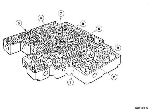
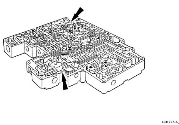
5. Remove the converter drain back valve and solenoid pressure supply screen.
6. Remove the main control valve body cover plate.
1. Remove the 13 bolts.
2. Remove the valve body cover plate and gasket.

 Assembly
1. CAUTION: Before beginning assembly, carry out and inspect the
following:
When building up subassemblies and assembling the transmission, ALWAYS use new
gaskets and seals.
All fasteners must be ti ...
Other materials:
Anti-Lock Control
Refer to Wiring Diagrams Cell 42 , Anti-Lock Brake for schematic and
connector information.
Special Tool(s)
Worldwide Diagnostic System
(WDS)
418-F224,
New Generation STAR (NGS)
Tester
418-F052, or equivalent scan
tool
73 Digita ...
Headlamps
Refer to Wiring Diagrams Cell 85 , Headlamps for schematic and
connector information.
Special Tool(s)
73III Automotive Meter or
equivalent
105-R0057
Inspection and Verification
1. Verify the customer concern by operating the headlamps. ...
Axle Housing
Special Tool(s)
Plug Set, Differential
205-294 (T89P-4850-B)
Protector, Differential Seal
(Pair)
205-461
Remover, Halfshaft
205-475
Remover, Steering Arm
211-003 (T64P-3590-F)
...
