Ford Mustang (1999-2004) Service Manual: Assembly
1. CAUTION: Before beginning assembly, carry out and inspect the following: When building up subassemblies and assembling the transmission, ALWAYS use new gaskets and seals.
All fasteners must be tightened to the torque specification indicated. In addition to appearing in the section, the necessary torques can be found in the General Specifications Chart.
When building up subassemblies, each component part should be lubricated with clean transmission fluid. It is also good practice to lubricate the subassemblies as they are installed in the case.
Needle bearings, thrust washers and seals should be lightly coated with petroleum jelly during subassembly buildup or transmission assembly.
Many components and surfaces in the transmission are precision machined. Careful handling during disassembly, cleaning, inspection and assembly can prevent unnecessary damage to machined surfaces.
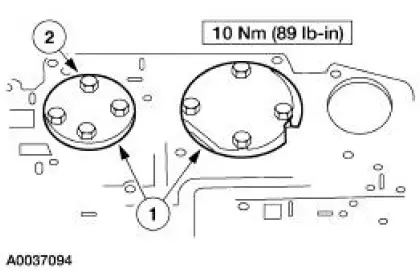
Install the valve body cover plate.
1. Position the valve body cover plate gasket and cover plate.
2. Install the two guide pin bolts.
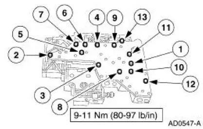
3. Install the bolts.
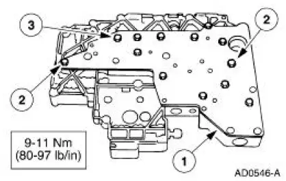
2. Tighten the bolts in the sequence shown.
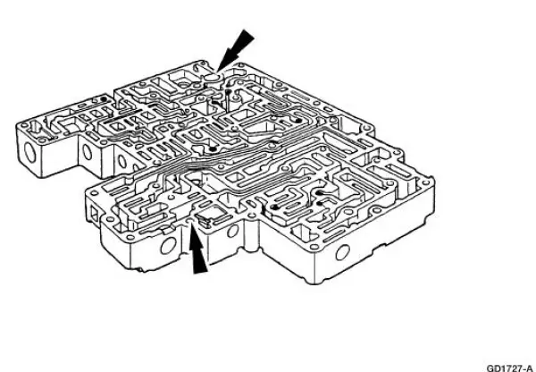
3. Install the eight coasting booster valve shuttle balls.

4. Install the converter drain back valve and solenoid pressure supply screen.
5. Install the separator plate and gaskets.
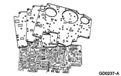
6. Install the two reinforcement plates.
1. Position the plates.
2. Install the bolts.
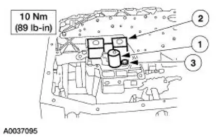
7. NOTE: Inspect the shift solenoid O-rings and TCC solenoid O-rings for damage.
Install the shift solenoid.
1. Position the TCC solenoid.
2. Position the shift solenoid.
3. Install the bolt.
 Disassembly
Main Control Valve Body - Disassembled View
1. Remove the torque converter clutch (TCC) solenoid and the shift solenoid.
1. Remove the bolt.
2. Remove the shift solenoid.
3. Remov ...
 Pump and Intermediate Clutch Piston
Special Tool(s)
Installer, Front Pump Fluid
Seal
307-014 (T63L-77837-A)
Protector, Piston Seal
307-339 (T95L-77005-A)
Pump and Intermediate Clutch Piston - Disassembled ...
Other materials:
Removal
1. Disconnect the electrical connectors from the EGR vacuum regulator
solenoid, the
supercharger bypass vacuum solenoid, and the differential pressure
feedback EGR system.
2. Disconnect the vacuum hoses from the differential pressure feedback EGR
sy ...
Noise, Vibration and Harshness (NVH) (Description and Operation)
Noise is any undesirable sound, usually unpleasant in nature. Vibration is
any motion, shaking or
trembling, that can be felt or seen when an object moves back and forth or up
and down. Harshness is
a ride quality issue where the vehicle's response to the ro ...
Frame and Mounting
Frame and Body Mounting
Torque Specifications
Frame Assembly
Underbody misalignment can affect front and rear wheel alignment, the
operation of the suspension
parts and drivetrain operation. Window glass cracks, door and window opening
concerns, and air or ...
