Ford Mustang (1999-2004) Service Manual: Driveshaft - Cobra
Material
| Item | Specification |
| Threadlock and Sealer E0AZ-19554-AA | WSK-M2G351-A5 (type II) |
| Silicone Lubricant (Aerosol) F5AZ-19553-AA | ESR-M13P4-A |
Removal and Installation
1. Raise and support the vehicle.
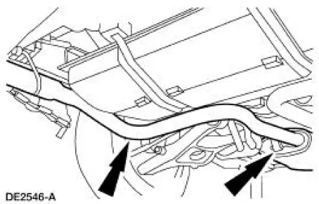
2. NOTE: To aid disassembly and assembly, lubricate the exhaust hangers with silicone lubricant.
Remove the two exhaust hangers from the rubber mounts.
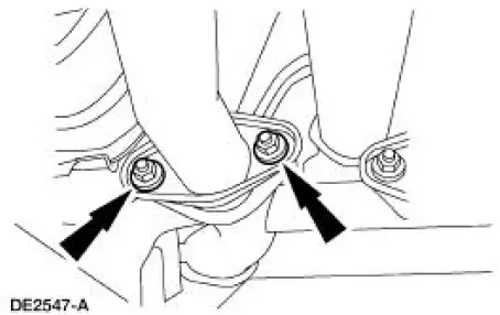
3. Remove the nuts on the left side exhaust.
4. Lower the muffler pipe enough to clear the flange. Move the muffler assembly forward to disconnect the third exhaust hanger.
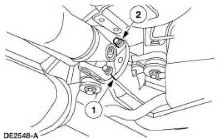
5. Carry out the following:
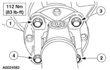
1. Place an index mark on the rear axle pinion flange and the driveshaft centering socket yoke.
2. Remove the four bolts.
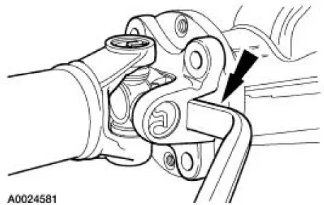
6. CAUTION: The driveshaft centering socket yoke fits tightly on the rear axle pinion flange pilot. Never hammer on the driveshaft or any of its components to disconnect the yoke from the flange. Pry only in the area shown, with a suitable tool, to disconnect the yoke from the flange.
Using a suitable tool as shown, disconnect the driveshaft centering socket yoke from the rear axle pinion flange.
7. CAUTION: Do not allow the slip yoke to bottom on the transmission output shaft.
Lower the rear end of the driveshaft to clear the rear axle housing. Pull the driveshaft rearward until the driveshaft slip yoke clears the transmission extension housing.
- Place a paint index mark on the driveshaft slip yoke and the transmission output shaft.
- Place a commercially available plug in the extension housing to prevent fluid leakage.
8. CAUTION: Install the driveshaft with new bolts. If new bolts are not available, apply threadlock and sealer to the threads of the original bolts.
CAUTION: Do not allow the slip yoke to bottom on the transmission output shaft.
CAUTION: The driveshaft centering socket yoke fits tightly on the rear axle pinion flange pilot. To make sure that the yoke seats squarely on the flange, tighten the bolts evenly in a cross pattern as shown.
NOTE: Clean all foreign material from the yoke areas of the driveshaft.
To install, reverse the removal procedure.
 Driveshaft (Removal and Installation)
Material
Item
Specification
Threadlock and
Sealer
E0AZ-19554-AA
WSK-M2G351-A5 (type
II)
Removal and Installation
1. Raise and support the vehicle.
2. Carry out the following:
...
 Driveshaft Slip Yoke
Special Tool(s)
Installer/Remover, C Frame
and Screw
205-086 (T74P-4635-C)
...
Other materials:
Removal
CAUTION: Suspension fasteners are critical parts because they affect
performance of vital
components and systems and their failure can result in major service expense. A
new part with
the same part number or an equivalent part must be installed, if installat ...
Engine Support Insulators
Special Tool(s)
3 Bar Engine Support Kit
303-F072
Engine Lift Bracket Set
303-D095 (D94L-6001-A) or
equivalent
...
Lamp Switch - Brake Pedal Position (BPP)
Removal
1. Disconnect the battery ground cable.
2. Remove the brake pedal position (BPP) switch.
1. Remove the clip.
2. Remove the retainer.
3. Disconnect the electrical connector.
4. Remove the BPP switch.
Installation
1. NOTE: When the b ...
