Ford Mustang (1999-2004) Service Manual: Engine (Assembly)
Special Tool(s)
 |
Guides, Connecting Rod 303-442 (T93P-6136-A) |
 |
Installer, Crankshaft Rear Oil Seal 303-518 (T95P-6701-DH) |
 |
Installer, Crankshaft Rear Oil Seal 303-516 (T95P-6701-BH) |
 |
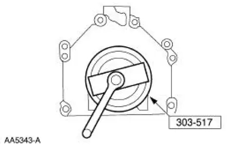
Installer, Crankshaft Rear Oil Slinger 303-517 (T95P-6701-CH) |
 |
Impact Slide Hammer 100-001 (T50T-100-A) |
 |
Spreader Bar 303-D089 (D93P-6001-A3) |
 |
Lifting Bracket, Engine 303-D087 (D93P-6001-A1) |
 |
Lifting Bracket, Engine 303-D088 (D93P-6001-A2) |
 |
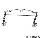
Lifting Bracket Set, Engine 303-D074 (D91P-6001-A) |
 |
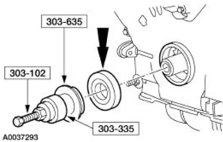
Installer, Crankshaft Vibration Damper 303-102 (T74P-6316-B) |
 |
Installer, Front Cover Oil Seal 303-335 (T88T-6701-A) |
 |
Compressor, Piston Ring 303-D032 (D81L-6002-C) or equivalent |
 |
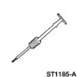
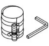
Holding Tool, Crankshaft 303-448 (T93P-6303-A) |
 |
Remover/Installer, Cylinder Head 303-572 (T97T-6000-A) |
 |
Compressor, Valve Spring 303-576 (T97P-6565-AH) |
 |
Strap Wrench 303-D055 (D85L-6000-A) or equialent |
 |
Crankshaft Seal Installer 303-635 |
Material
| Item | Specification |
| Silicone Gasket and Sealant F7AZ-19554-EA or equivalent | WSE-M4G323- A4 |
| Super Premium SAE 5W-20 Motor Oil XO-5W20-QSP or equivalent | WSS-M2C153-H |
Assembly
NOTE: During engine assembly, it may by necessary to check bearing clearances and end play. For additional information, refer to Section.
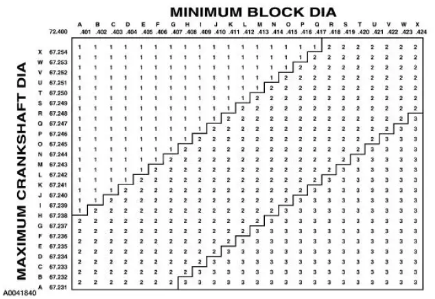
1. Record the main bearing code found on the front of the engine block.
2. Record the main bearing code found on the back of the crankshaft.
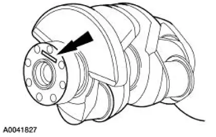
3. Using the data recorded earlier and the Bearing Select Fit Chart, Standard Bearings Chart determine the required bearing grade for each main bearing.
- Read the first letter of the engine block main bearing code and the first letter of the crankshaft main bearing code.
- Read down the column below the engine block main bearing code letter, and across the row next to the crankshaft main bearing code letter, until the two intersect. This is the required bearing grade for the number one crankshaft main bearing.
- As an example, if the engine block code letter is "F" and the crankshaft code letter is "D," the correct bearing grade for this main bearing is "2."
- Repeat this process for the remaining four main bearings.
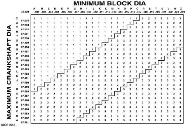
4. If oversize bearings are being used, use the procedure in the previous step and the Bearing Select Fit Chart, Oversize Bearing Chart to determine the required grade for each main bearing.
NOTE: Before assembling the cylinder block, all sealing surfaces must be free from chips, dirt, paint and foreign material. Also, make sure the coolant and oil passages are clear.
5. Install the crankshaft upper main bearings into the cylinder block and lubricate them with clean engine oil.
6. NOTE: Do not install the upper thrust washer until the crankshaft is installed. Refer to Step 3.
NOTE: Do not install the upper thrust washer until the crankshaft (6303) is installed. Refer to Step 3.
Install the crankshaft onto the upper main bearings.
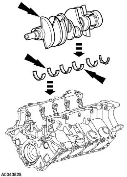
7. NOTE: The oil groove on the thrust washer must face toward the rear of the engine (against the crankshaft surface).
Push the crankshaft rearward and install the crankshaft upper thrust washer at the rear of the No. 5 main boss.
8. NOTE: Rotate the jackscrews into the bearing caps enough to provide clearance to the cylinder block prior to installing the bearing caps.
Install the lower main bearings into the main bearing caps and lubricate them with clean engine oil.
9. Install the rear main bearing cap.
10. Install the remaining main bearing caps on the cylinder block and tap into place using a plastic or dead-blow hammer.
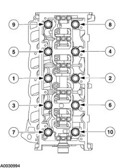
11. Install the vertical main bearing cap fasteners and tighten in the sequence shown.
- Tighten to 40 Nm (30 lb-ft).
- Tighten an additional 85-95 degrees.
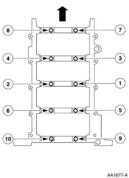
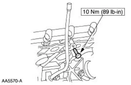
12. Back out the jackscrews against the cylinder block in sequence shown.
- Tighten to 5 Nm (44 lb-in).
- Tighten to 10 Nm (89 lb-in).
13. Install the side bolts and tighten them in the sequence shown.
14. Check the crankshaft end play. For additional information, refer to Section.
15. Check the piston to cylinder block and piston ring clearances.
16. Install the piston rings.
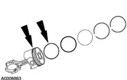
17. Make sure the ring gaps (oil spacer [A], oil ring [B], and compression ring [C]) are properly spaced around the circumference of the piston.
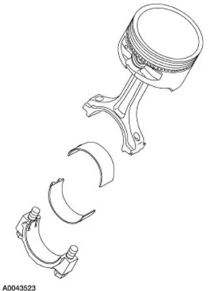
18. CAUTION: Do not scratch the cylinder walls or the crankshaft journals with the connecting rod.
NOTE: Only one piston and connecting rod shown, others similar.
NOTE: Make sure the crankshaft is facing forward.
NOTE: Lubricate the piston rings, cylinder walls and connecting rod bearings with clean engine oil.
Install the upper bearings in the connecting rod as shown.
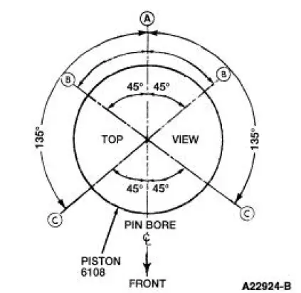
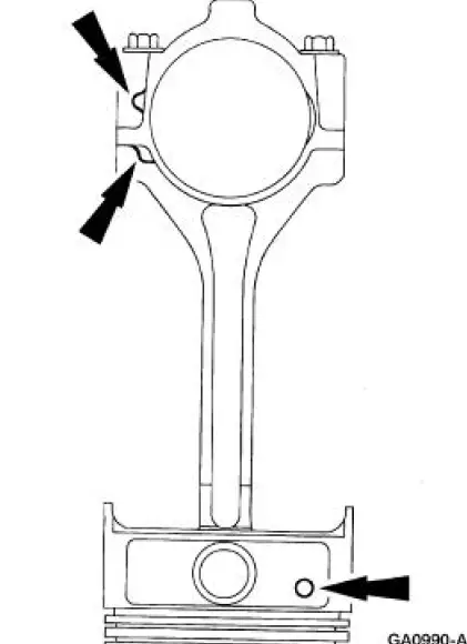
19. NOTE: The piston grade number will face the rear of the engine.
Check that the piston/connecting rod assembly is oriented with the identification marks facing the front of the engine.
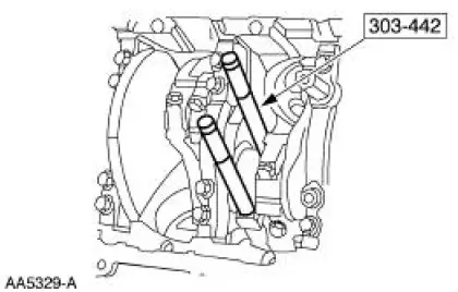
20. CAUTION: Do not scratch the cylinder walls or the crankshaft journals with the connecting rod.
NOTE: Make sure the crankshaft is at TDC.
NOTE: Only one connecting rod assembly shown, others similar.
Using the special tool install the piston and connecting rod assembly by pushing the pistons through the top of the cylinder block.
21. NOTE: These bolts are torque-to-yield. Install new bolts each time they are serviced.
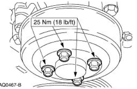
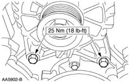
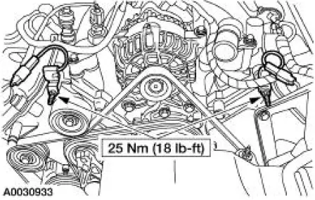
Install the connecting rod bearing caps and bolts and tighten in three stages.
- Stage 1: Tighten to 25Nm (18 lb-ft).
- Stage 2: Tighten to 40Nm (30 lb-ft).
- Stage 3: Tighten an additional 90 degrees.
22. Rotate the crankshaft and install the remaining piston and connecting rod assemblies.
23. Check the connecting rod bearing clearance. For additional information, refer to Section.
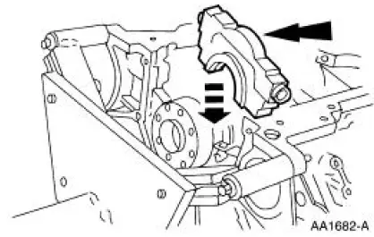
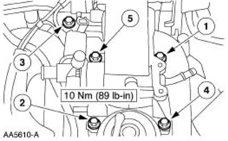
24. Install the oil pump and tighten the bolts.
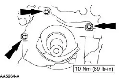
25. NOTE: Install a new O-ring if necessary.
Install the oil pump screen cover and tube.
26. NOTE: If not secured within four minutes, sealant must be removed and sealing area cleaned with metal surface cleaner. Allow to dry until there are no signs of wetness, or four minutes, whichever is longer. Failure to follow this procedure can cause future oil leakage.
If the retainer plate was removed, apply a 4 mm (0.16 in) bead of silicone gasket and sealant around the rear oil seal retainer sealing surface.
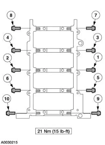
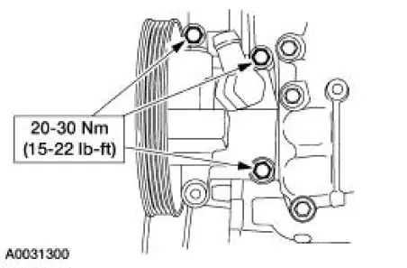
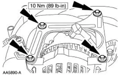
27. Install the rear main seal retainer plate. Tighten the bolts in the sequence shown.
- Tighten bolts 1-6 to 10 Nm (89 lb-in).
- Hand-tighten bolts 7 and 8.
- Tighten bolts 7 and 8 to 20 Nm (15 lb-ft).
- Tighten bolts 7 and 8 an additional 60 degrees.
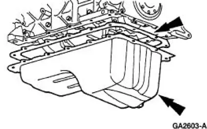
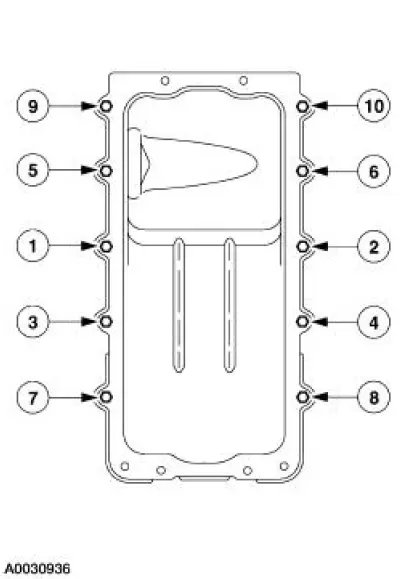
28. Install the oil pan and gasket and loosely install the bolts.
29. Tighten the bolts in the sequence shown.
- Tighten to 20 Nm (15 lb-ft).
- Rotate an additional 60 degrees.
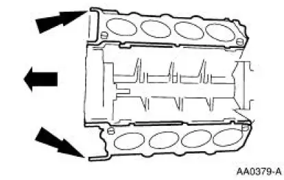
30. Install the cylinder head gaskets.
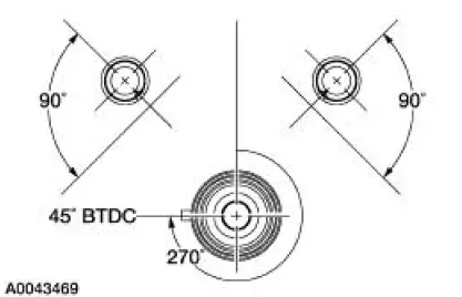
31. CAUTION: Cylinder head to cylinder block pre-assembly must be followed exactly or damage to valves and pistons can result.
CAUTION: Camshaft keyways must maintain a 90 degree clocked position relative to the valve cover rail.
CAUTION: To prevent piston crown and valve damage the crankshaft keyway must be clocked at 270 (45 BTDC) before the installation of the cylinder head assembly.
NOTE: Crankshaft must be rotated clockwise only.
Align the keyways as shown.
32. NOTE: Position the RH and the LH cylinder heads over the dowels on the cylinder head gaskets.
NOTE: The LH is shown the RH is similar.
Tighten the bolts in six stages in the sequence shown.
- Stage 1: Tighten to 40 Nm (30 lb-ft).
- Stage 2: Tighten an additional 90 degrees.
- Stage 3: Loosen the bolts a minimum of one full turn.
- Stage 4: Tighten to 40 Nm (30 lb-ft).
- Stage 5: Tighten an additional 90 degrees.
- Stage 6: Tighten an additional 90 degrees.
33. CAUTION: Timing chain procedures must be followed exactly or damage to valves and pistons will result.
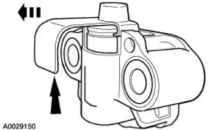
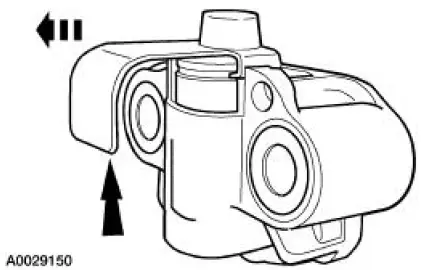
Using a vise, compress the tensioner plunger.
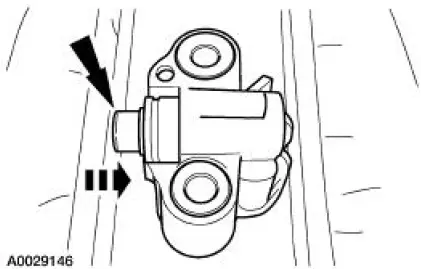
34. Install a retaining clip on the tensioner to hold the plunger in during installation.
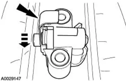
35. Remove the tensioner from the vise.
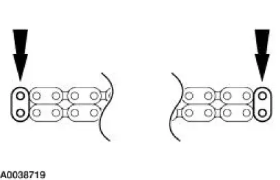
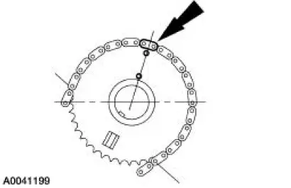
36. NOTE: There are 58 links in each timing chain.
If the copper links are not visible, mark one link on one end and one link on the other end to use as timing marks.
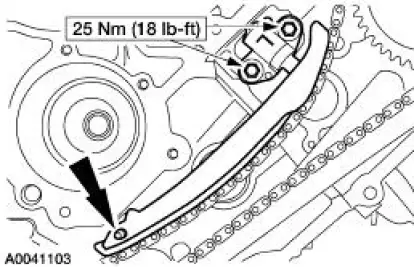
37. Install the timing chain guides.
1. Position the LH timing chain guide.
2. Install and tighten the LH bolts.
3. Position the RH timing chain guide.
4. Install and tighten the RH bolts.
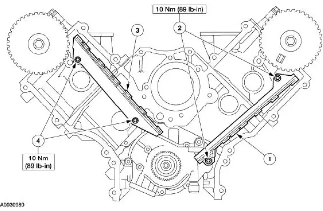
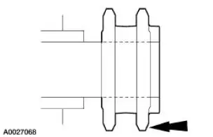
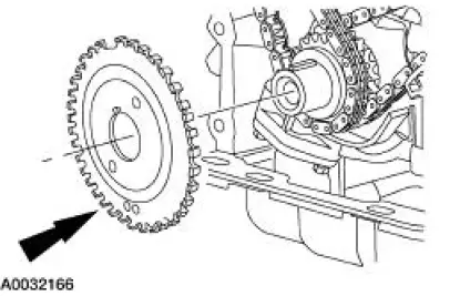
38. Install the crankshaft sprocket, making sure the flange faces forward.
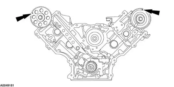
39. Rotate the RH camshaft sprocket until the timing mark is approximately at the 11 o'clock position. Rotate the LH camshaft sprocket until the timing mark is approximately at the 12 o'clock position.
40. CAUTION: Unless otherwise instructed, do not rotate either the crankshaft or the camshafts, when the timing chains are removed and the cylinder heads are installed.
Severe piston and valve damage will occur.
CAUTION: When instructed to do so, rotate the crankshaft counterclockwise only. Do not rotate past the position shown or severe piston and valve damage can occur.
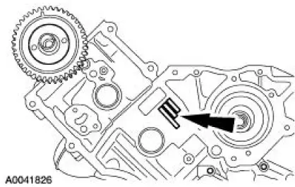
NOTE: The number one cylinder is at top dead center (TDC) when the stud on the engine block fits into the slot in the handle of the special tool.
Using the special tool, position the crankshaft so the number one cylinder is at TDC.
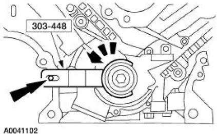
41. Remove the special tool.
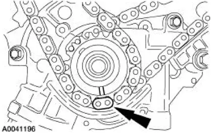
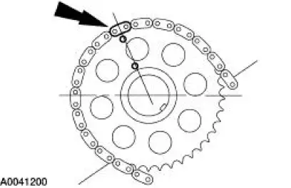
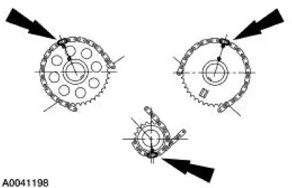
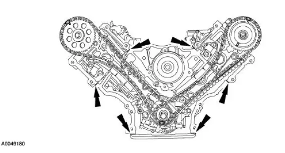
42. Position the LH (inner) timing chain on the crankshaft sprocket, aligning the copper (marked) link with the timing mark on the sprocket.
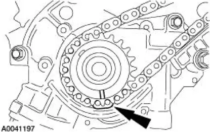
43. Install the LH timing chain on the camshaft sprocket, aligning the copper (marked) link with the timing marks on the sprocket.
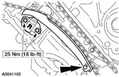
44. NOTE: The LH timing chain tensioner arm has a bump near the dowel hole for identification.
Position the LH timing chain tensioner arm on the dowel pin and install the LH timing chain tensioner.
45. Remove the retaining clip from the LH timing chain tensioner
46. Position the RH (outer) timing chain on the crankshaft sprocket, aligning the copper (marked) link with the timing mark on the sprocket.
47. Install the RH timing chain on the camshaft sprocket, aligning the copper (marked) link with the timing marks on the sprocket.
48. Position the RH timing chain tensioner arm on the dowel pin and install the RH timing chain tensioner.
49. Remove the retaining clip from the RH timing chain tensioner.
50. Make sure that the copper (marked) chain links are lined up with the dots on the crankshaft sprockets and the camshaft sprocket.
51. NOTE: Sensor ring teeth must face forward.
Position the crankshaft sensor ring on the crankshaft.
52. NOTE: The front cover must be installed within four minutes of applying sealant.
Apply silicone gasket and sealant in the locations shown.
53. Install a new engine front cover gasket on the engine front cover.
54. Install the engine front cover.
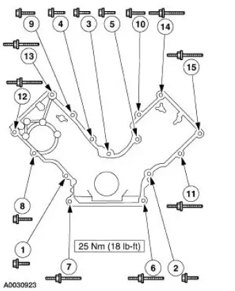
55. Tighten the four oil pan bolts in the sequence shown in three stages.
- Stage 1: Tighten to 2 Nm (18 lb-in).
- Stage 2: Tighten to 20 Nm (15 lb-ft).
- Stage 3: Tighten an additional 60 degrees.
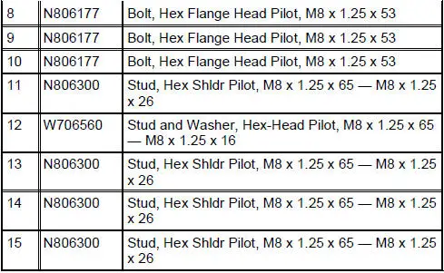
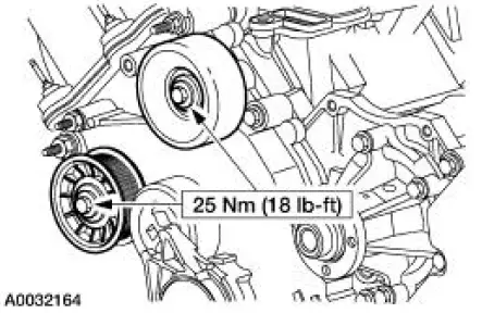
56. Install the belt idler pulleys.
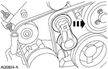
57. Lubricate the engine front cover and the front oil seal inner lip with clean engine oil.
58. Using the special tool, install the front oil seal.
59. Install the water pump pulley and bolts.
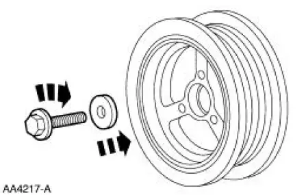
60. NOTE: The crankshaft pulley must be installed within four minutes of applying sealant.
Apply silicone gasket and sealant to the Woodruff key slot on the crankshaft pulley.
61. Using the special tool, install the crankshaft pulley.
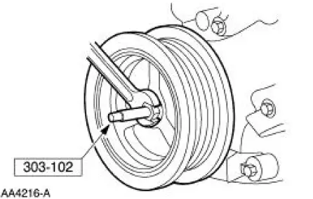
62. NOTE: Use special tool 303-009 or a suitable strap wrench to hold the crankshaft pulley.
Install the washer and the bolt. Tighten the bolt in four stages.
- Stage 1: Tighten to 90 Nm (66 lb-ft).
- Stage 2: Loosen one full turn.
- Stage 3: Tighten to 50 Nm (37 lb-ft).
- Stage 4: Tighten an additional 90 degrees.
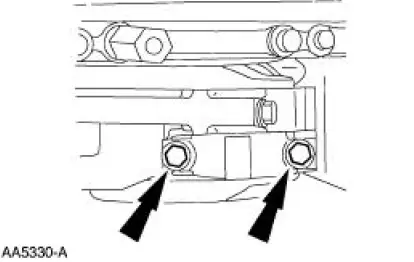
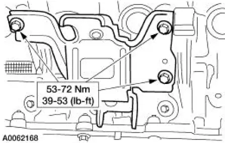
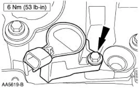
63. Install the LH engine mount.
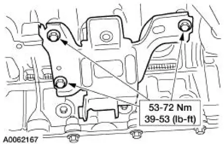
64. Install the RH engine mount.
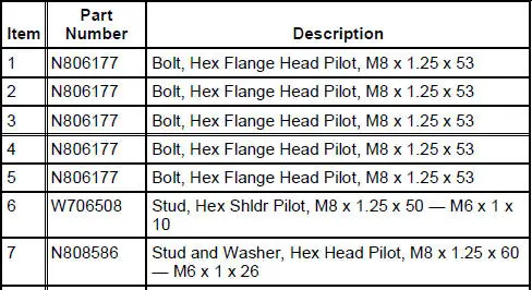
65. NOTE: Only three bolts are required for installation.
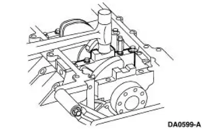
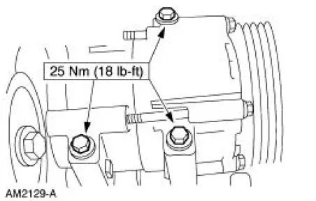
Install the power steering pump.
- Position the power steering pump.
- Install the bolts.
66. Lubricate the O-ring seal with PAG compressor oil, YN-12C, F7AZ-19589-DA or equivalent meeting Ford specification WSH-M1C231-B.
Install the A/C compressor.
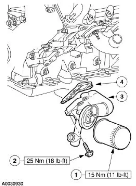
67. Install the oil filter adapter.
68. Install the camshaft roller followers.
1. Install the special tool.
2. Compress the valve spring.
3. Install the camshaft follower
69. NOTE: One spark plug shown, others similar.
Install spark plugs.
70. NOTE: The RH side is shown, the LH side is similar.
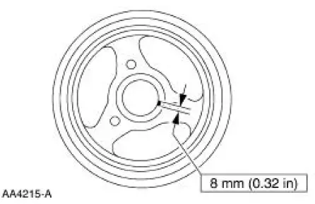
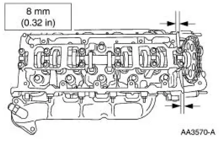
Apply an eight millimeter bead of silicone gasket and sealant at the intersection of the engine front cover and the cylinder head.
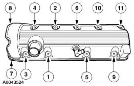
71. NOTE: RH valve cover shown, LH similar.
Install the valve covers.
72. NOTE: Lubricate the O-ring seal with clean engine oil.
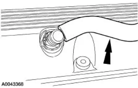
Install a new O-ring.
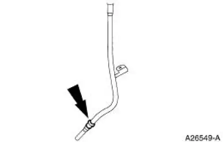
73. Install the tube.
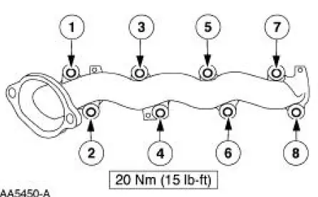
74. NOTE: RH exhaust manifold shown, LH similar. Tighten the bolts in the sequence shown.
Install the LH exhaust manifold.
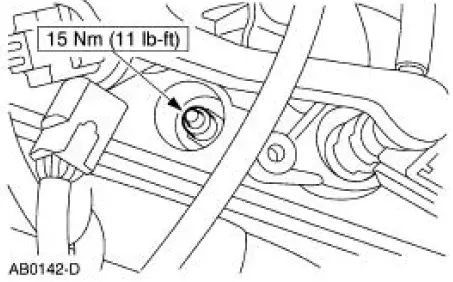
75. Connect the lower end of the EGR tube to the LH exhaust manifold.
76. Inspect the O-ring seals and install new O-ring seals as necessary.
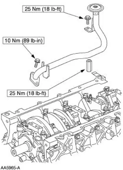
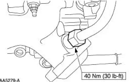
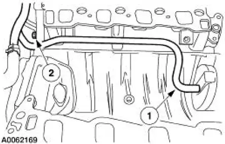
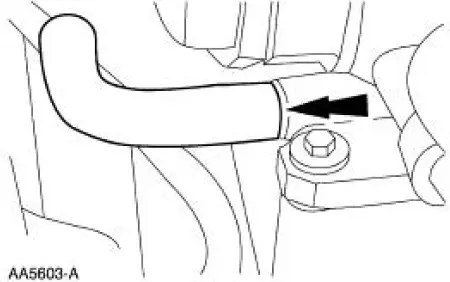
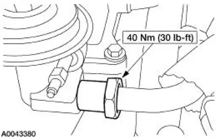
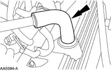
77. Install the water bypass tube.
1. Instal the bypass tube.
2. Install the nut.
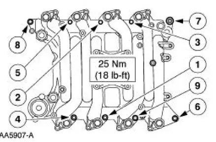
78. Install the intake manifold and gaskets. Tighten the bolts in the sequence shown.
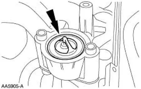
79. NOTE: The O-ring is to be installed on top of the thermostat.
Install the water thermostat and O-ring.
- Install a new O-ring as necessary.
80. Install the water outlet connector.
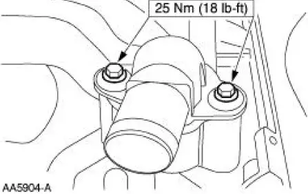
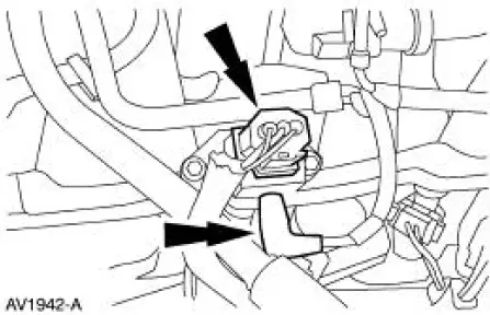
81. Install the bolts and the generator.
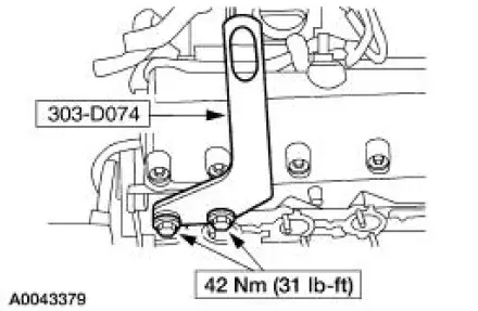
82. Install the generator support brace.
83. Install the accessory drive belt. For additional information, refer to Section
84. Install the radio interference capacitors.
85. Install the ignition coils and bolts.
86. Position the throttle body and install the bolts, tighten in the sequence shown.
87. Connect the vacuum line to the fuel pressure sensor.
88. Connect the PCV hose.
89. Connect the PCV hose to the base of the throttle body.
90. Connect the EGR tube to the EGR valve.
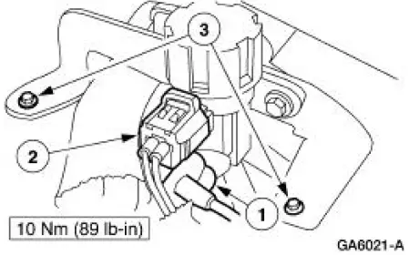
91. Install the EGR vacuum regulator solenoid.
1. Install the vacuum hoses.
2. Install the electrical connector.
3. Install the bolts.
92. Connect the hoses from the differential pressure feedback EGR transducer.
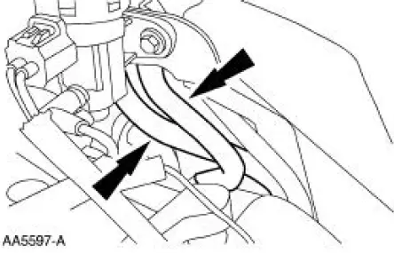
93. Connect the differential pressure feedback EGR electrical connector.
94. Install the breather tube.
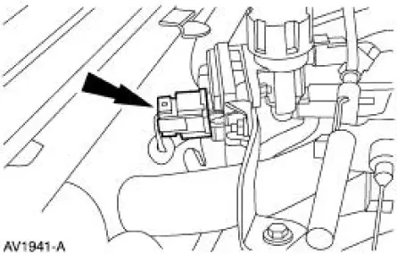
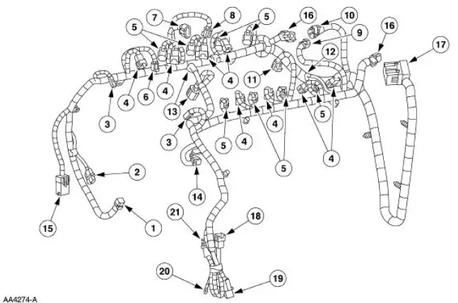
95. Install the engine control sensor wiring.
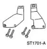
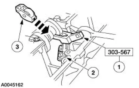
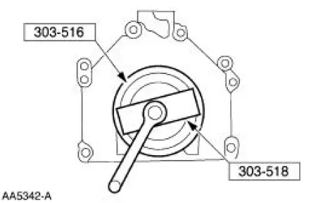
96. Install the RH and LH special tools.
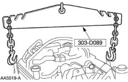
97. Using the special tool, remove the engine from the stand.
98. Using the special tool, install the crankshaft rear main seal.
- Lubricate the oil seal using clean engine oil.
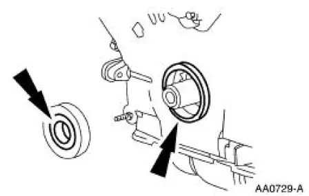
99. Using the special tools, install the crankshaft rear oil slinger.
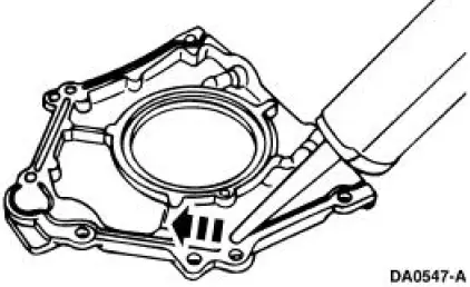
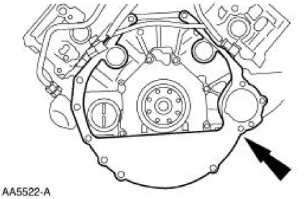
100. Install the separator plate.
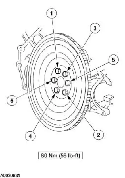
101. Install the flywheel.
 Piston
Material
Item
Specification
Super Premium SAE 5W-20
Motor Oil
XO-5W20-QSP or equivalent
WSS-M2C153-
H
Disassembly
1. Press the piston pin out of the connecting rod and piston a ...
 Cylinder Heads (Installation)
Special Tool(s)
Installer, Crankshaft Vibration
Damper
303-102 (T74P-6316-B)
Installer, Front Cover Oil Seal
303-335 (T88T-6701-A)
Holding Tool, Crankshaft
3 ...
Other materials:
Manual Transmission
The TR3650 five-speed manual transmission features the following:
The fifth speed gear functions as an overdrive gear.
The forward gears are synchronized and helical cut.
The reverse gear operates through a constant-mesh, fully
synchronized system.
...
Dual Converter Y-Pipe - 3.8L
Removal
NOTE: The RH and LH catalytic converters are serviceable separately.
1. Raise and support the vehicle. For additional information, refer to
Section.
2. CAUTION: When repairing the exhaust system or removing exhaust
components,
disconnect all heated o ...
Inspection and Verification
1. The keyless entry system is a generic electronic module (GEM).
2. Verify the customer concern by using the remote transmitters to
operate the keyless entry
system.
3. Visually inspect for the following obvious signs of mechanical and
electrica ...
