Ford Mustang (1999-2004) Service Manual: Engine - 4.6L (2V)
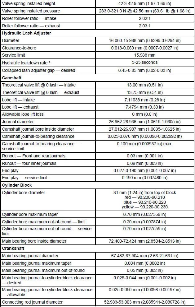
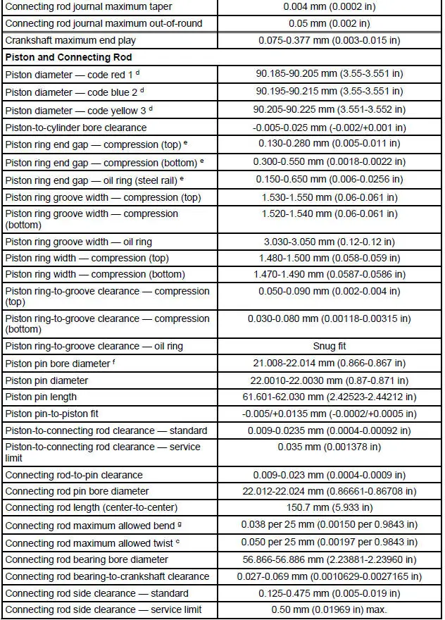
General Specifications
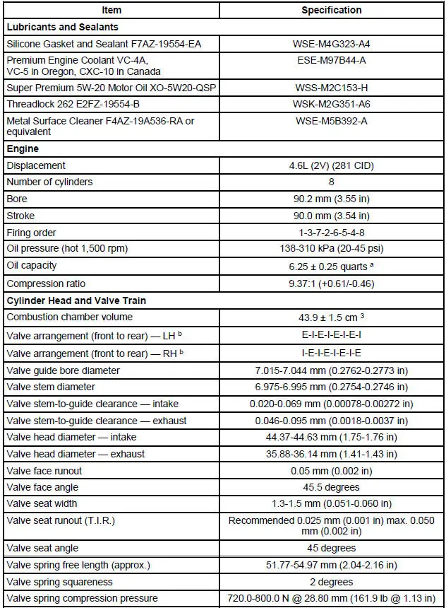
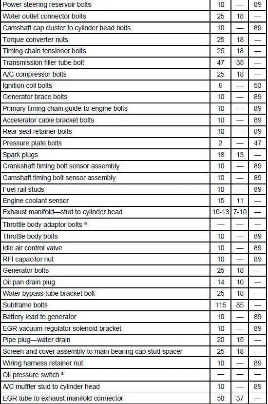
a - With installation of a new filter.
b - Distance front edge of bearing is installed below front face of cylinder block.
c - Time necessary for plunger to leak down 1.6 mm of travel with 222 N force and leak down fluid in tappet.
d - Measured at 31.5 mm from top of block. Measured at 43 mm from top of piston, at 90 degrees to the piston pin.
e - Specification in 90.200 mm diameter gauge.
f - If applicable, measured vertically, +0.030-0.050 mm (0.001-0.002 inch) measured horizontally (oval pin bore).
g - Pin bore and crank bearing bore must be parallel and in same vertical plane within the specified total difference when measured at the ends of a 203 mm bar, 101.5 mm on each side of rod centerline.
Torque Specifications
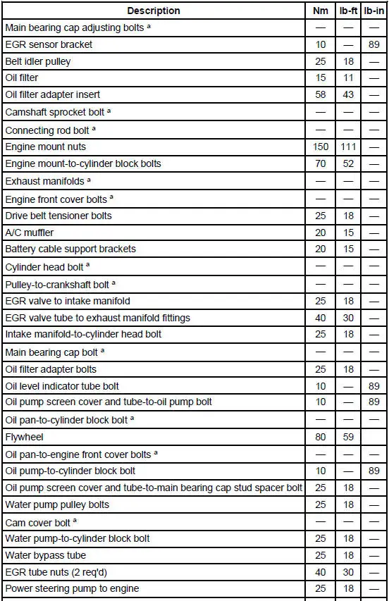
a - Refer to the procedure in this section.
- Engine
- Intake Manifold
- Valve Cover RH
- Valve Cover LH
- Crankshaft Pulley
- Crankshaft Front Oil Seal
- Engine Front Cover
- Timing Drive Components
- Valve Seals
- Hydraulic Lash Adjuster
- Camshaft Roller Follower
- Camshaft
- Exhaust Manifold RH
- Exhaust Manifold LH
- Oil Filter Adapter
- Oil Level Indicator and Tube
- Oil Pan
- Flywheel
- Flexplate
- Engine Mount RH
- Engine Mount LH
- Cylinder Heads (Removal)
- Engine (Removal)
- Engine (Disassembly)
- Cylinder Head (Disassembly and Assembly of Subassemblies)
- Piston
- Engine (Assembly)
- Cylinder Heads (Installation)
- Engine (Installation)
 Engine (Installation)
Special Tool(s)
Heavy Duty Floor Crane
014-00071 or equivalent
Spreader Bar
303-D089 (D93P-6001-A3) or
equivalent
Material
Item
Specification
SAE 5W-20 Pre ...
 Engine
A modular engine is built around four modules:
the intake module
the cylinder head module (RH)
the cylinder head module (LH)
the lower engine module
While no ...
Other materials:
Moulding - Rocker Panel
Removal
1. Remove the front rocker panel moulding screw.
2. Remove the strip.
3. Remove the rear rocker panel moulding screw.
4. Remove the pin-type retainers and the rocker panel moulding.
Installation
1. To install, reverse the removal procedure. ...
Installation
NOTE: Do not use a fiber disc to clean the surfaces. Fibers from
the disc can get into the oil pan and
oil and clog the oil bypass valve.
1. Clean and inspect the cylinder head for flatness.
2. Install a new head gasket on the cylinder block with the sm ...
Radiator
Material
Item
Specification
Motorcraft Premium Gold
Engine Coolant
VC-7-A (in Oregon VC-7-B)
(yellow color)
WSS-M97B51-
A1
Removal and Installation
NOTE: Radiator removal and installation is similar for both 3.8L and
4.6L vehicles. ...
