Ford Mustang (1999-2004) Service Manual: Piston
Material
| Item | Specification |
| Super Premium SAE 5W-20 Motor Oil XO-5W20-QSP or equivalent | WSS-M2C153- H |
Disassembly
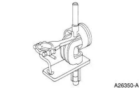
1. Press the piston pin out of the connecting rod and piston assembly.
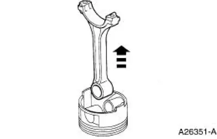
2. Remove the connecting rod from the piston.
3. Clean and inspect the piston and connecting rod. For additional information, refer to Section.
Assembly
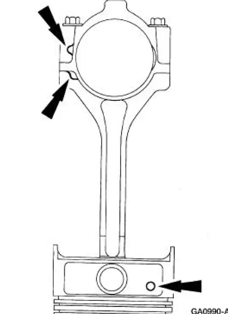
1. NOTE: Connecting rod must be installed into piston with identification markings toward front.
Position the connecting rod in the piston.
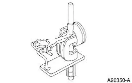
2. Press the piston into the piston and connecting rod assembly.
3. Install the piston rings.
1. Using a suitable ring expander tool install the upper compression ring with the top side identification mark towards the dome.
2. Using a suitable ring expander tool install the lower compression ring with the top side identification mark towards the dome.
3. NOTE: Assemble with end gaps up.
Using a suitable tool install the piston oil control segment ring spacer.
4. NOTE: Install one segment ring above and one segment ring below the spacer.
Using a suitable tool install the piston oil control segment rings.
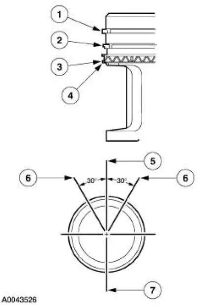
5. Orient the upper compression ring gap to the center line at the rear of the piston, parallel to the wrist pin bore.
6. Orient the oil control ring gaps as shown.
7. Orient the expander ring gap and lower compression ring gap as shown.
 Cylinder Head (Disassembly and Assembly of Subassemblies)
Special Tool(s)
Compressor, Valve Spring
303-381(T91P-6565-A)
Compressor Spacer, Valve
Spring
303-382 (T91P-6565-AH)
Installer, Valve Stem Oil Seal
303-383 ( ...
 Engine (Assembly)
Special Tool(s)
Guides, Connecting Rod
303-442 (T93P-6136-A)
Installer, Crankshaft Rear Oil
Seal
303-518 (T95P-6701-DH)
Installer, Crankshaft Rear Oil
Seal
...
Other materials:
Removal
WARNING: Always wear safety glasses when repairing an air bag
supplemental restraint
system (SRS) vehicle and when handling an air bag module. This will
reduce the risk of injury
in the event of an accidental deployment.
WARNING: Carry a live air ...
Inspection and Verification
1. Verify the customer concern is with the evaporative emission (EVAP)
system.
2. Visually inspect for the following obvious signs of mechanical damage.
Visual Inspection Chart
Mechanical
Fuel filler cap
EVAP test port
...
Water Pump - 3.8L
Material
Item
Specification
Motorcraft Premium Gold
Engine Coolant
VC-7-A (in Oregon VC-7-B)
(yellow color)
WSS-M97B51-
A1
Removal and Installation
1. Drain the engine coolant. For additional information, refer to Cooling
System Dra ...
