Ford Mustang (1999-2004) Service Manual: Engine (Disassembly)
Special Tool(s)
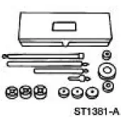 |
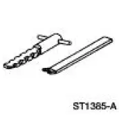
Service Set, Camshaft 303-017 (T65L-6250-A) |
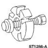 |
Remover, Crankshaft Vibration Damper 303-009 (T58P-6316-D) |
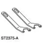 |
Lifting Bracket Set, Engine 303-D095 (D94L-6001-A) or equivalent |
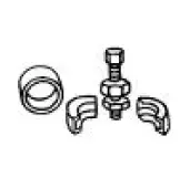 |
Remover, Power Steering Pump Pulley 211-016 (T69L-10300-B) |
 |
Remover, Oil Seal 303-409 (T92C-6700-CH) |
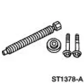 |
Remover, Crankshaft Vibration Damper 303-176 (T82L-6316-B) |
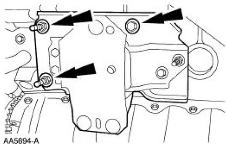
1. Remove the bolts and the LH engine support insulator.
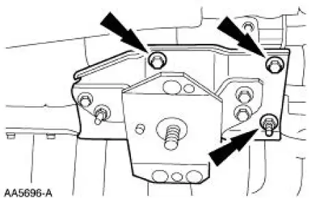
2. Remove the bolts and the RH engine support insulator.
3. Remove the special tool.
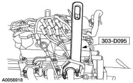
4. Remove the special tool.
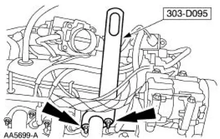
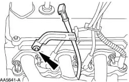
5. Remove the bolt and the oil level indicator and tube. Discard the O-ring.
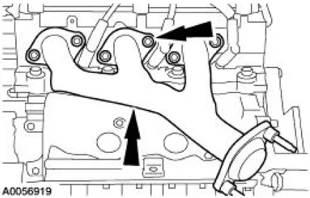
6. Remove the bolts and the LH exhaust manifold. Discard the gasket.
7. Disconnect the exhaust gas recirculation (EGR) tube.
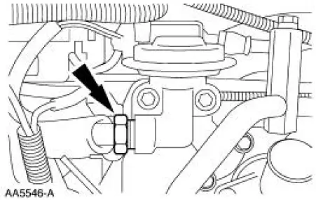
8. Remove the EGR tube.
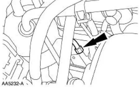
9. Remove the nuts and the RH exhaust manifold. Discard the gasket.
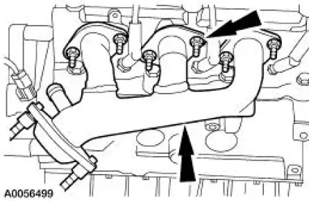
10. Disconnect the idle air control (IAC) valve and throttle position (TP) sensor electrical connectors.
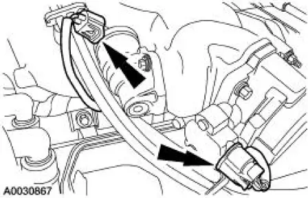
11. Position the RH spark plug wires aside.
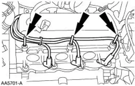
12. Position the LH spark plug wires aside.
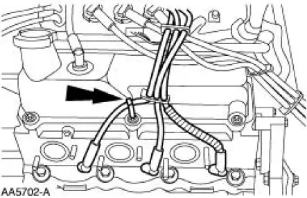
13. Disconnect the ignition coil and the radio interference capacitor electrical connectors.
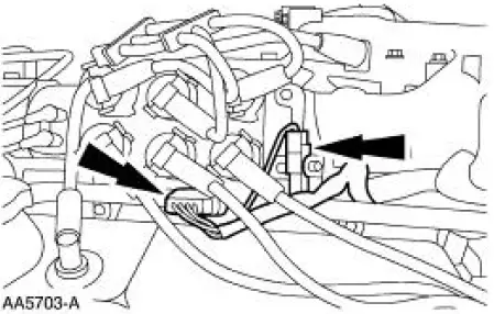
14. Remove the positive crankcase ventilation (PCV) tube.
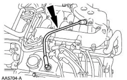
15. Disconnect the vacuum hoses.
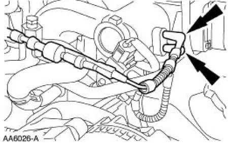
16. Disconnect the differential pressure feedback EGR system electrical and vacuum connections.
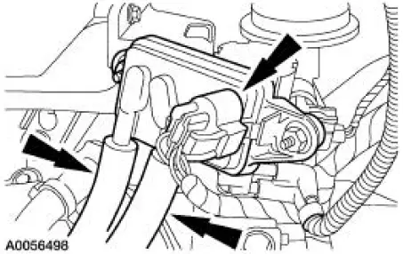
17. Disconnect the EGR vacuum regulator solenoid electrical and vacuum connections.
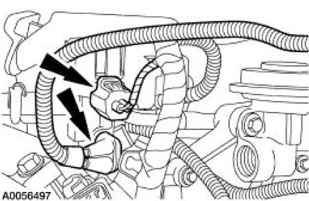
18. NOTE: Record the location of the long bolts and the short bolts.
Remove the upper intake manifold and the upper intake manifold gasket.
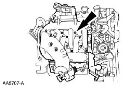
19. Remove the fuel injection supply manifold and the fuel injectors. 20. Disconnect the cylinder head temperature (CHT) sensor.
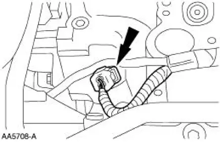
21. Disconnect the camshaft position (CMP) sensor electrical connector.
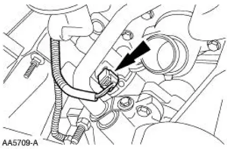
22. Disconnect the engine oil pressure sender electrical connector.
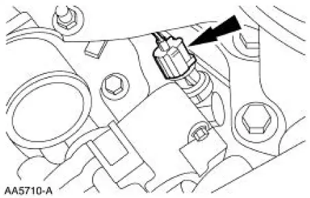
23. Remove the pin-type retainer.
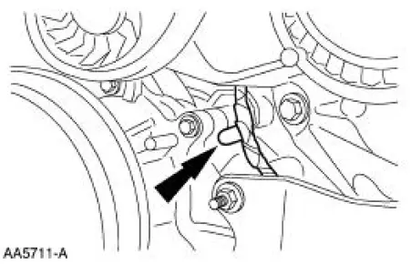
24. Disconnect the crankshaft position (CKP) sensor electrical connector.
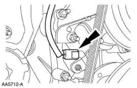
25. Remove the engine wiring harness.
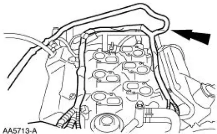
26. Remove the stud bolt.
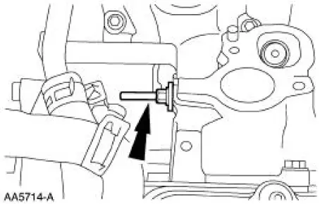
27. Remove the heater water outlet tube.
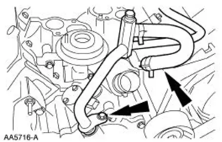
28. NOTE: Record the location of the long bolts and the short bolts.
Remove the lower intake manifold and the intake manifold gasket.
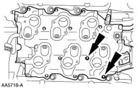
29. Remove the accessory drive belt.
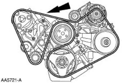
30. Remove the water pump pulley.
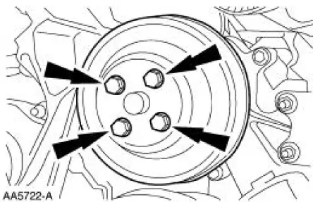
31. Remove the A/C compressor bracket.
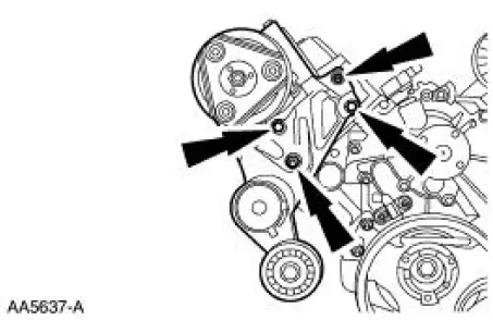
32. Using the special tool, remove the power steering pump pulley.
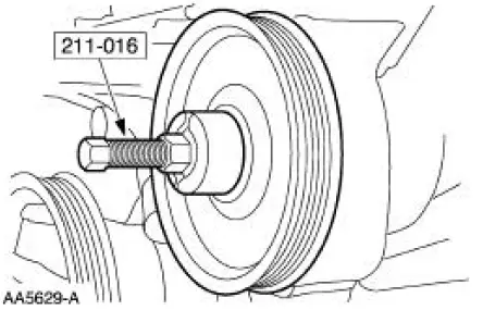
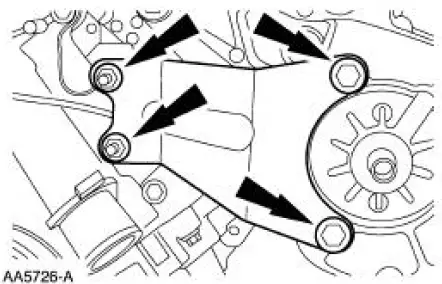
33. Remove the power steering pump bracket.
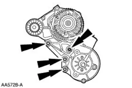
34. Remove the bolts and the generator mounting bracket.
35. Remove the crankshaft pulley bolt.
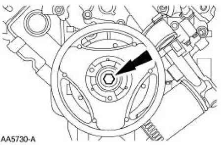
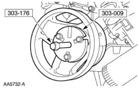
36. Using the special tool, remove the crankshaft pulley.
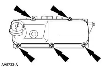
37. Remove the RH and the LH valve covers.
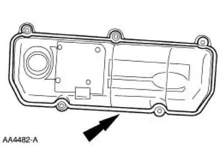
38. Inspect the valve cover gaskets. Install new gaskets if necessary.
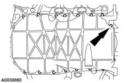
39. Remove the bolts and the oil pan.
40. CAUTION: If the components are to be reinstalled, they must be installed into the same position. Mark the components for location.
Remove the LH rocker arms.
1. Remove the bolts.
2. Remove the rocker arms.
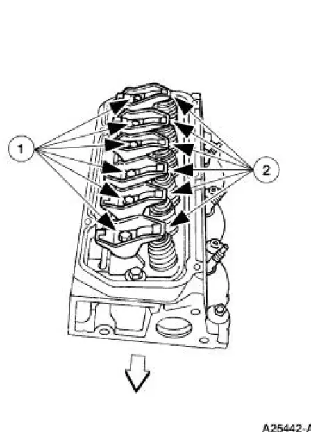
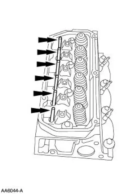
41. Remove the LH push rods.
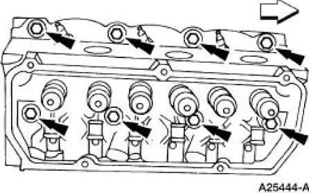
42. NOTE: Record the location of the long bolts and the short bolts.
Remove and discard the LH cylinder head bolts.
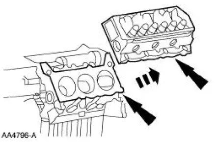
43. Remove the LH cylinder head and gasket. Discard the gasket.
44. Remove the RH rocker arms.
1. Remove the bolts.
2. Remove the rocker arms.
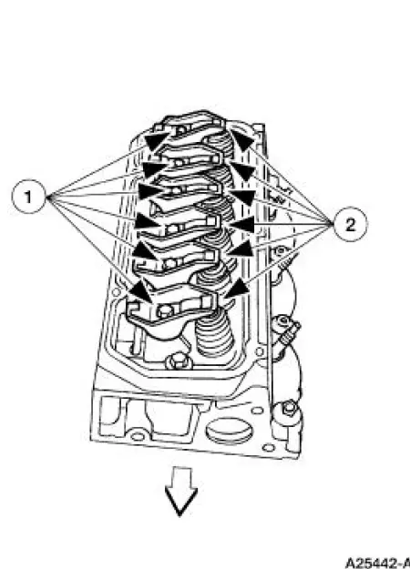
45. Remove the RH push rods.
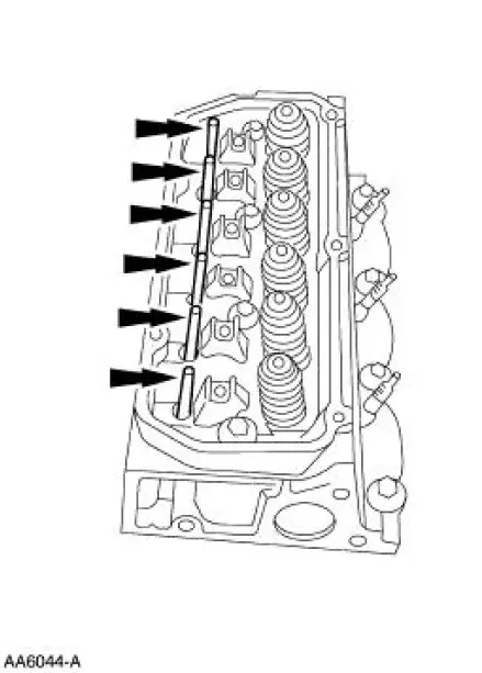
46. NOTE: Record the location of the long bolts and the short bolts.
Remove and discard the RH cylinder head bolts.
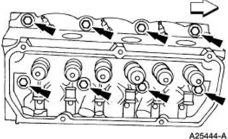
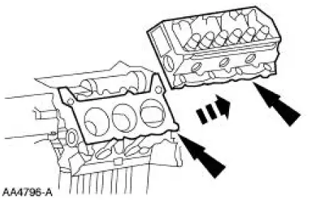
47. Remove the RH cylinder head and gasket. Discard the gasket.
48. Remove the camshaft synchronizer.
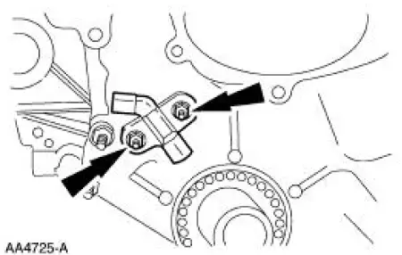
49. Remove the bolts and the crankshaft position sensor.
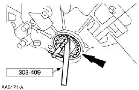
50. Using the special tool, remove the crankshaft front seal.
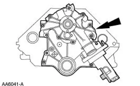
51. Remove the bolts and the front cover assembly and gasket.
52. Remove the camshaft position sensor drive gear.
1. Remove the bolt.
2. Remove the camshaft position sensor drive gear.
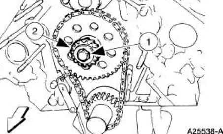
53. Compress and install a retaining pin to hold the timing chain tensioner.
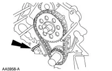
54. Remove the camshaft sprocket, the crankshaft sprocket and the timing chain as an assembly.
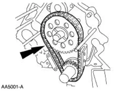
55. Remove the timing chain tensioner.
1. Remove the bolts.
2. Remove the timing chain tensioner.
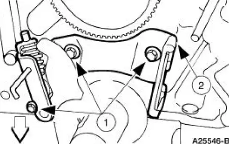
56. Remove the engine dynamic balance shaft.
- Remove the bolts.
- Remove the balance shaft driven gear, thrust plate and engine dynamic balance shaft as an assembly.
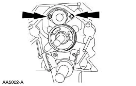
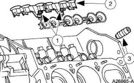
57. Remove the valve tappets.
1. Remove the bolts.
2. Remove the tappet guide plates and retainers.
3. Remove the valve tappets.
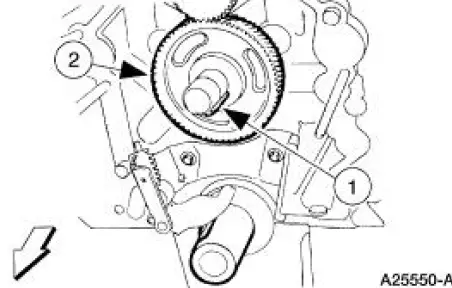
58. Remove the engine balance shaft drive gear.
1. Remove the camshaft keyway.
2. Remove the gear.
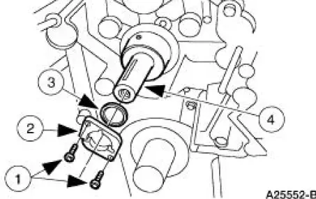
59. Remove the camshaft.
1. Remove the bolts.
2. Remove the camshaft thrust plate.
3. Remove the spacer.
4. Remove the camshaft.
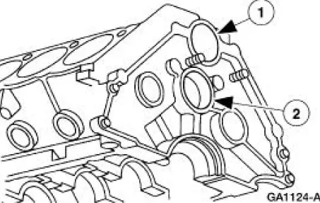
60. Remove the bearing covers.
1. Remove the engine dynamic balance shaft bearing cover.
2. Remove the camshaft bearing cover.
61. Remove the oil pump screen cover and tube.
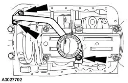
62. Remove the oil pan bridge and baffle assembly.
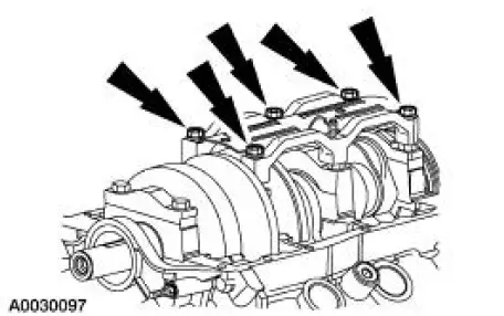
63. CAUTION: The connecting rods and bearings are matched to the crankshaft journals. Make sure the components are marked and installed in the correct location.
CAUTION: Each connecting rod and connecting rod cap are matched sets. They will fit together only one way. Mark them before removing.
CAUTION: Care should be taken not to damage the connecting rod and the connecting rod cap fractured joint face surface or engine damage may occur.
NOTE: Before removing the pistons, inspect the top of the cylinder bores. If necessary, remove the ridge or carbon deposits from each cylinder, using a cylinder ridge reamer and following the manufacturer's instructions.
Remove the pistons.
1. Make sure the piston being removed is at the bottom of the cylinder bore.
2. Remove the bolts.
3. Remove the connecting rod cap and the lower connecting rod bearing.
4. CAUTION: Be careful to avoid damage to the cylinder wall when removing the piston.
Push the piston and the connecting rod out of the cylinder.
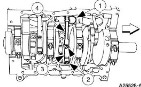
64. Repeat the removal steps for the remaining pistons.
65. CAUTION: The crankshaft main bearings and the main bearing caps are matched to the crankshaft journals. Make sure the components are marked for position.
NOTE: The crankshaft main bearing located at the rear main bearing cap is the thrust bearing.
Remove the four main bearing caps and lower crankshaft main bearings.
1. Remove the stud bolts.
2. Remove the main bearing cap and the lower crankshaft main bearing.
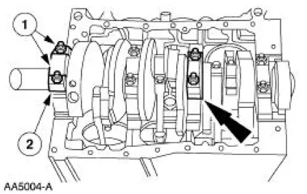
66. Repeat the main bearing cap and the lower bearing removal steps for the remaining main bearing caps and the crankshaft lower main bearings.
67. CAUTION: The crankshaft journals must be protected from damage when the crankshaft is removed.
Remove the crankshaft and the crankshaft rear seal.
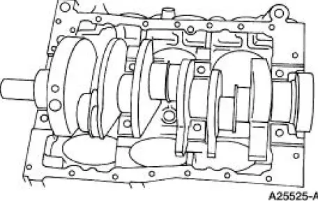
68. NOTE: For ease in assembly, record the location of the crankshaft upper thrust bearing.
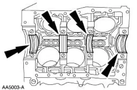
Remove the crankshaft upper main bearings and the crankshaft upper thrust bearing.
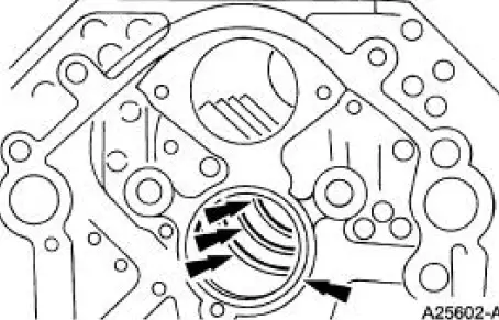
69. Using the camshaft bearing service set, remove the camshaft bearings.
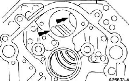
70. Using the camshaft bearing service set, remove the engine dynamic balance shaft bearings.
71. If equipped, remove the engine block heater.
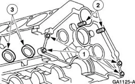
72. NOTE: For cleaning purposes, the plugs should be removed.
If necessary, remove the following:
1. the cylinder block dowels.
2. the oil gallery plugs.
3. the water jacket plugs.
 Engine (Removal)
Special Tool(s)
Lifting Bracket Set, Engine
303-D095 (D94L-6001-A) or
equivalent
Spreader Bar
303-D089 (D93P-6001-A3) or
equivalent
Heavy Duty Floor Crane
...
 Cylinder Head
Special Tool(s)
Compressor, Valve Spring
303-163 (T81P-6513-A)
Material
Item
Specification
SAE 5W-20 Premium Synthetic
Blend Motor Oil
XO-5W20-QSP or equivalent
WSS- ...
Other materials:
Vacuum Control Motor - Air Inlet Duct Door
Removal
1. Remove the instrument panel.
2. Disconnect the vacuum hose.
3. Disconnect the control arm.
4. Remove the vacuum control motor.
Remove the screws.
Installation
1. To install, reverse the removal procedure. ...
Air Intake Scoop Bracket
Removal and Installation
1. Remove the air intake scoop. For additional information, refer to Air
Intake Scoop in this section.
2. Remove the air intake scoop bracket nut at the throttle body.
3. Remove the exhaust gas recirculation (EGR) vacuum regulat ...
Switch - Key-In-Ignition Warning
Removal
1. Remove the ignition switch lock cylinder.
1. Insert the ignition key and turn to the RUN position.
2. Insert a punch in the access hole of the steering column and
press the release tab while
pulling out the ignition switch lock cy ...
