Ford Mustang (1999-2004) Service Manual: Front Seat Cushion
Disassembly and Assembly
All vehicles
1. Remove the seat track. For additional information, refer to Seat Track in this section.
2. Remove the seat backrest. For additional information, refer to Front Seat Backrest in this section.
Vehicles with power seat
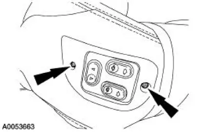
3. Remove the screws in the power seat control switch.
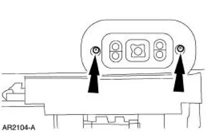
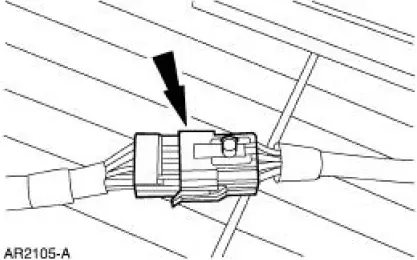
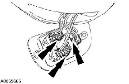
4. Disconnect the electrical connector and remove the power seat control switch.
Vehicles with standard power lumbar
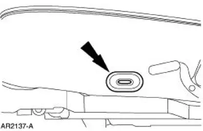
5. Remove the lumbar control switch (14C715).
6. Disconnect the power lumbar support air hoses.
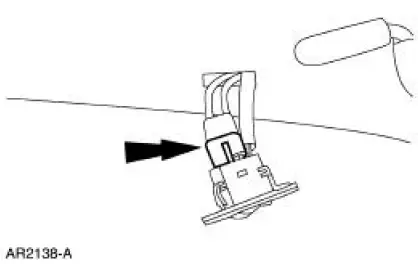
7. Disconnect the lumbar seat control switch electrical connector and remove the lumbar control switch.
Vehicles with power bolster and lumbar
NOTE: For vehicles with lumbar and bolster, the pump and solenoid module are serviced as part of the seat cushion frame.
8. Remove the power lumbar and bolster seat switch screws.
9. Disconnect the lumbar and bolster control switches.
All vehicles
10. Remove the J-clips.
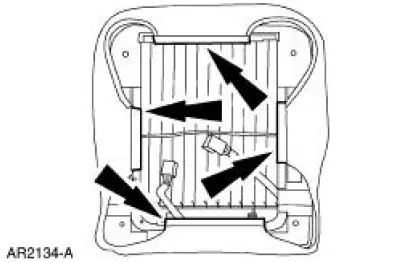
11. Remove the hog rings.
12. Remove the front seat cushion cover (62900) from the front seat cushion pad (632A22).
13. Remove the front seat cushion frame and spring (63100).
Vehicles with power cushion bolster
14. Disconnect the hoses from the two bolster adjuster pads (one shown) and slide the bolster adjuster pad up and off the seat cushion frame.
All vehicles
15. To assemble, reverse the disassembly procedure.
 Latch - Front Seat Backrest
Removal
NOTE: The power seat backrest adjuster assembly must be installed as a
new unit. Repair of the
power seat backrest adjuster assembly components is not acceptable and
should not be attemp ...
 Front Seat Backrest
Disassembly and Assembly
All vehicles
1. Remove the front seat backrest. For additional information, refer to
Front Seat Backrest in this
section.
2. Remove the front seat backrest head restrai ...
Other materials:
Axle Housing
Special Tool(s)
Plug Set, Differential
205-294 (T89P-4850-B)
Protector, Differential Seal
(Pair)
205-461
Remover, Halfshaft
205-475
Remover, Steering Arm
211-003 (T64P-3590-F)
...
Evaporator Core Housing
Disassembly
1. Remove the evaporator core housing. For additional information, refer to
Evaporator Core
Housing in this section.
2. Remove the foam weather seal.
3. Remove the screws and remove the heater core.
4. Remove the screws and remove the A/C rec ...
Lighting control
A. Off
B. Parking lamps, instrument panel
lamps, license plate lamps and tail
lamps
C. Headlamps
High Beams
• Push the lever toward the
instrument panel to switch
on the high beams.
• Pull the lever toward you to
switch of the high beams.
Headlamp Flashe ...
