Ford Mustang (1999-2004) Service Manual: Engine (Removal)
Special Tool(s)
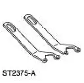 |
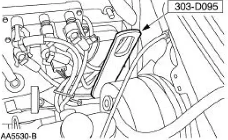
Lifting Bracket Set, Engine 303-D095 (D94L-6001-A) or equivalent |
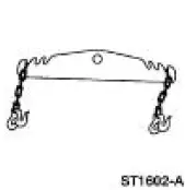 |
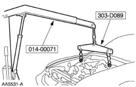
Spreader Bar 303-D089 (D93P-6001-A3) or equivalent |
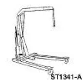 |
Heavy Duty Floor Crane 014-00071 or equivalent |
Removal
WARNING: Do not smoke or carry lighted tobacco or open flame of any type when working on or near any fuel related components. Highly flammable mixtures are always present and may be ignited, resulting in possible personal injury.
All vehicles
1. Drain the engine cooling system.
2. Recover the A/C refrigerant.
3. Disconnect the battery negative cable (14301).
4. Relieve the fuel pressure.
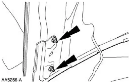
5. Disconnect the hood ground strap.
6. Remove the hood (16612).
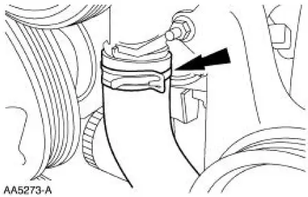
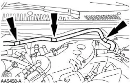
7. Disconnect the vacuum hose.
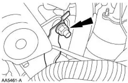
8. Disconnect the generator (10346).
1. Disconnect the connectors.
2. Remove the nut.
3. Remove the battery positive cable.
9. NOTE: Place a suitable container under the pump.
Disconnect the power steering pump (3A674).
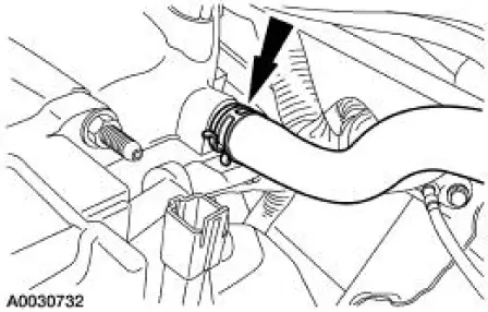
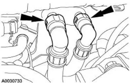
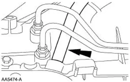
10. Disconnect the lower radiator hose (8286).
11. Disconnect the upper radiator hose (8620).
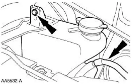
12. Remove the radiator coolant recovery reservoir (8A080).
13. Disconnect the accelerator cable and, if equipped, the speed control cable.
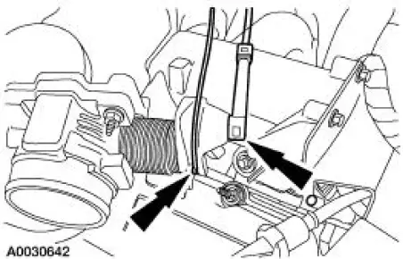
14. Position the accelerator cable bracket (9723) aside.
- Remove the bolts.
15. Remove the air cleaner outlet tube (9B659) and the air cleaner assembly.
16. Disconnect the A/C manifold and tube (19D734).
17. Disconnect the A/C compressor electrical connector.
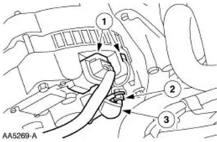
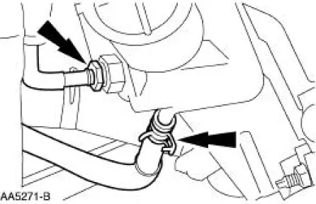
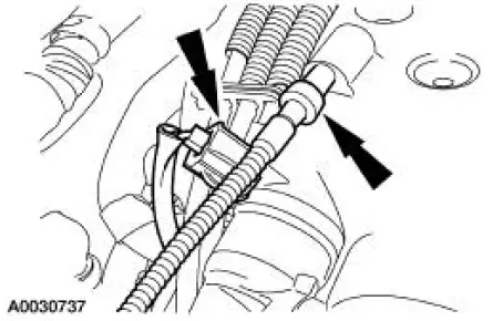
18. Disconnect the fuel supply line (9J337).
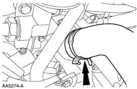
19. Disconnect the heater hoses (12270).
20. Disconnect the following connectors:
- 42-pin electrical connector
- 16-pin electrical connector
- 8-pin electrical connector
- A/C pressure switch
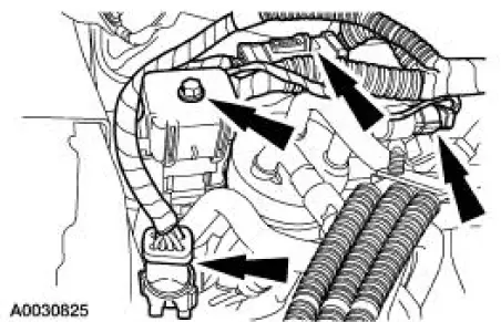
21. Position the wire harness aside.
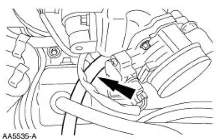
22. Disconnect the connector and the vacuum tube.
23. Disconnect the evaporative emissions (EVAP) return tube (9G271).
24. Raise the vehicle on a hoist.
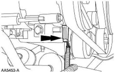
25. Remove the starter motor (11002). .
26. Remove the dual converter Y-pipe (5F250).
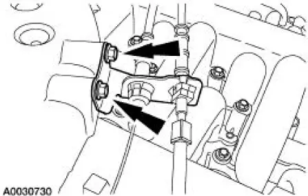
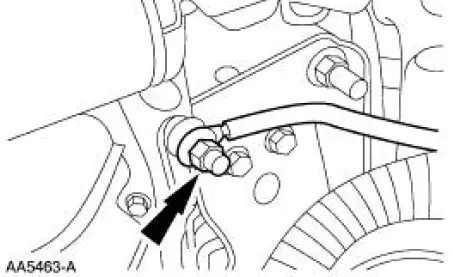
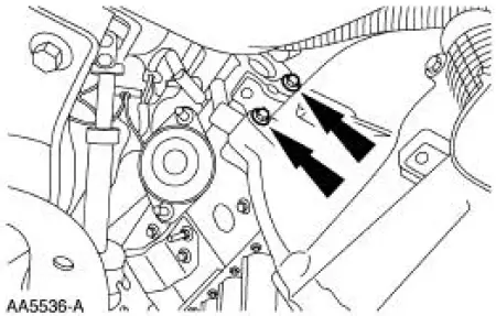
27. Remove the bracket.
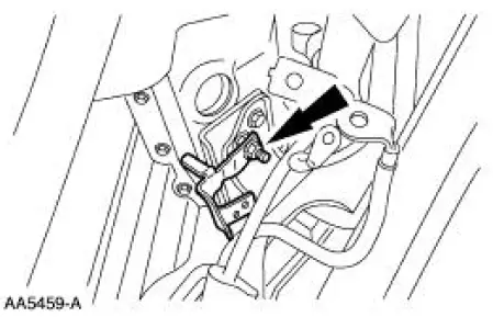
28. Remove the bracket.
- Remove the nut.
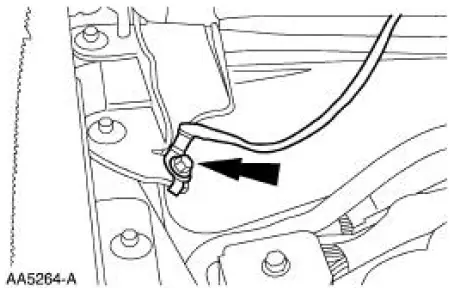
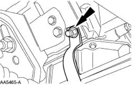
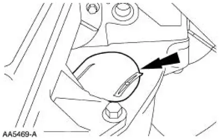
29. Disconnect the engine ground strap.
- Remove the nut.
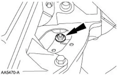
30. Remove the bracket.
Vehicles equipped with manual transmission
31. Remove the transmission.
32. Drain the engine oil.
- Remove the oil drain plug.
Vehicle equipped with automatic transmission
33. Remove the access cover.
34. NOTE: Discard the torque converter nuts.
Disconnect the torque converter (7902).
- Remove the four nuts.
35. Remove the oil pan-to-transmission bolts.
36. Remove the upper bell housing bolts.
37. Remove the transmission oil filler tube (7A228).
All vehicles
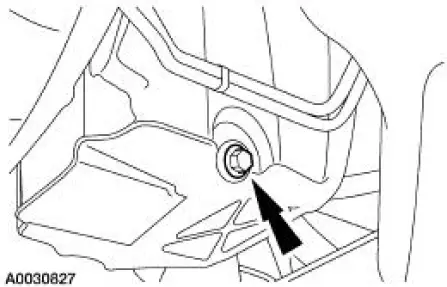
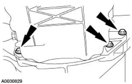
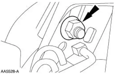
38. Remove the RH engine mount nut.
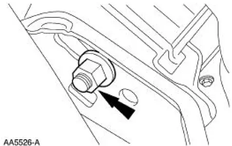
39. Remove the LH engine mount nut.
40. Lower the vehicle.
41. Support the transmission.
42. Install the special tool.
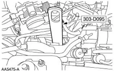
43. Install the special tools.
44. Using the special tool, remove the engine.
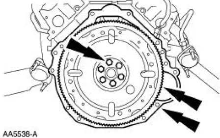
45. If necessary, remove the flywheel (6375) and the separator plate (6A372).
- Remove the bolts.
46. Mount the engine on a suitable engine stand.
 Installation
1. Install the RH engine insulator.
Install the nuts.
Install the bolts.
2. Install the LH engine insulator.
3. Connect the engine ground strap.
4. Install the bracket.
5. Lower the ve ...
 Engine (Disassembly)
Special Tool(s)
Service Set, Camshaft
303-017 (T65L-6250-A)
Remover, Crankshaft Vibration
Damper
303-009 (T58P-6316-D)
Lifting Bracket Set, Engine
303-D095 ( ...
Other materials:
Crankshaft Runout
Special Tool(s)
Dial Indicator Gauge with
Holding Fixture
100-002 (TOOL-4201-C) or
equivalent
1. NOTE: Crankshaft main bearing journals must be within
specifications before checking runout.
Use the Dial Indicator Gauge with Holding Fixtur ...
Differential Case and Ring Gear - Traction-Lok
Special Tool(s)
2-Jaw Puller
205-D072 (D97L-4221-A) or
equivalent
Gauge, Differential Clutch
205-022 (T66L-4204-A)
Gauge, Differential Clutch
205-135 (T80P-4946-A)
Installer, Differential Side
Bearing
205-010 (T57 ...
Inspection and Verification
1. Verify the customer concern by operating the wiper/washer system.
2. Visually inspect for obvious signs of mechanical and electrical
damage.
Visual Inspection Chart
Mechanical
Electrical
Hoses to windshield washer pump
Wiper l ...
