
Ford Mustang (1999-2004) Service Manual: Installation
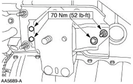
1. Install the RH engine insulator.
- Install the nuts.
- Install the bolts.
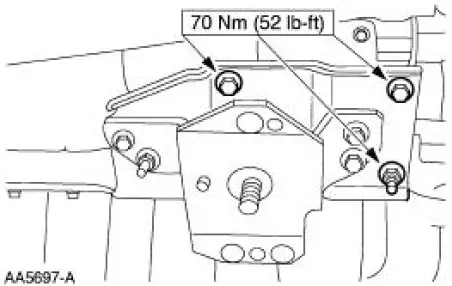
2. Install the LH engine insulator.
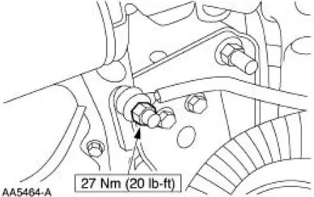
3. Connect the engine ground strap.
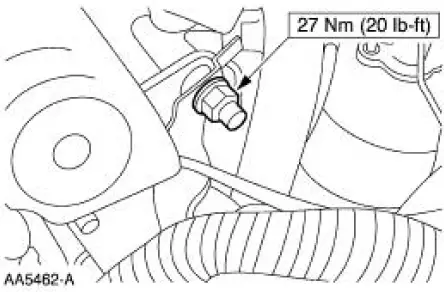
4. Install the bracket.
5. Lower the vehicle.
6. Lower the engine.
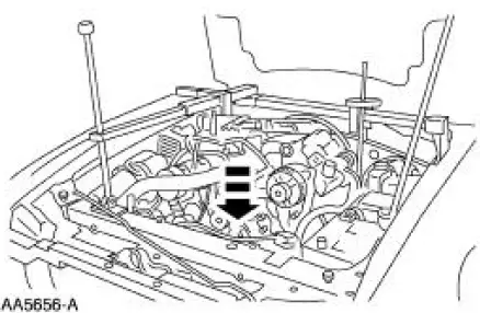
7. Raise the vehicle.
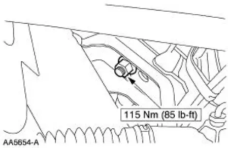
8. Install the RH engine mount nut.
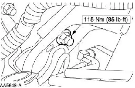
9. Install the LH engine mount nut.
10. Lower the vehicle.
11. Remove the special tools.
12. Install the coolant recovery reservoir.
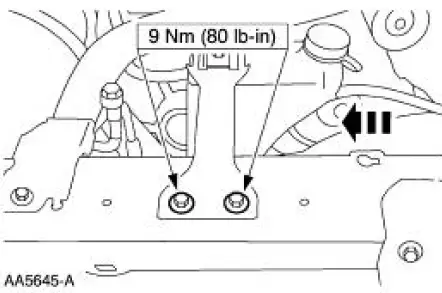
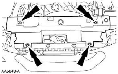
13. Install the radiator sight shield.
14. Install the air cleaner outlet tube.
15. Connect the battery ground cable.
 Removal
1. Disconnect the battery ground cable (14301).
2. Remove the air cleaner outlet tube (9B659).
3. Remove the radiator sight shield (8C291).
4. Remove the coolant recovery reservoir (8A080).
...
 Engine (Removal)
Special Tool(s)
Lifting Bracket Set, Engine
303-D095 (D94L-6001-A) or
equivalent
Spreader Bar
303-D089 (D93P-6001-A3) or
equivalent
Heavy Duty Floor Crane
...
Other materials:
Halfshaft
Special Tool(s)
Differential Plug
205-294 (T89P-4850-B)
Differential Seal Protector
205-461
Front Hub Remover
205-D070 (D93P-1175-B) or
Equivalent
Halfshaft Removal Tool
205-475
Steering Arm Remover
211-0 ...
Assembly
1. Carry out the following before reassembling:
Inspect the gears for broken or cracked teeth. Check for unusual wear
patterns.
Inspect the thrust washers for face wear, cracks, scoring and for signs
of heat damage.
Inspect the bearings, bearing cups a ...
Connect
1. Install the A/C tube lock coupling spring.
2. Lubricate the inside of the coupling with PAG Refrigerant Compressor Oil
(R-134a Systems) or
equivalent.
3. CAUTION: Use only the new O-ring seals. The use of any O-ring seals
other than
those specified in ...
