Ford Mustang (1999-2004) Service Manual: Evaporative Emission System Leak Test
Special Tool(s)
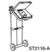 |
Evaporative Emission System Tester 310-F007 (134-00056) or equivalent |
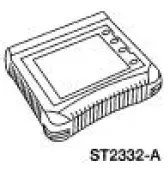 |
Worldwide Diagnostic System (WDS) 418-F224, New Generation STAR (NGS) Tester 418-F052, or equivalent scan tool |
CAUTION: The evaporative emission system must not be pressurized to more than 3.48 kPa (14 inches H 2 O) or damage to the evaporative emission system may occur.
1. Connect the Evaporative Emission System Leak Tester to the evaporative emission test port.
2. Close the canister vent solenoid. For additional information, refer to Canister Vent Solenoid Closing Procedure in this section.
3. Pressurize the evaporative emission system to 3.48 kPa (14 inches H 2 O).
4. Monitor the system for two minutes. The system fails the leak test if the pressure falls below 2.0 kPa (8 inches H 2 O).
5. Repair any leaks as necessary.
6. Repeat the leak test until the system remains above 2.0 kPa (8 inches H 2 O) after the twominute test period.
 Canister Vent Solenoid Closing Procedure
Special Tool(s)
Worldwide Diagnostic System
(WDS)
418-F224,
New Generation STAR (NGS)
Tester
418-F052, or equivalent scan
tool
CAUTION: The canister vent solenoid must not be ...
 Evaporative Emission Repair Verification Drive Cycle
Special Tool(s)
Worldwide Diagnostic System
(WDS)
418-F224,
New Generation STAR (NGS)
Tester
418-F052, or equivalent scan
tool
Drive Cycle Recommendations
NOTE: The followi ...
Other materials:
Traction Control
PRINCIPLES OF OPERATION
The traction control system helps avoid drive wheel spin and loss of
traction.
If your vehicle begins to slide, the system applies the brakes to individual
wheels and, when needed, reduces engine power at the same time. If the
wheels s ...
Lamp Assembly - Map/Dome
Removal
1. Disconnect the battery ground cable.
2. Remove the lamp lens from the lamp assembly.
3. Remove the lamp assembly.
1. Remove the screws.
2. Remove the lamp assembly.
Disconnect the electrical connectors.
Installation
1. NOTE ...
Deactivation
WARNING: Always wear safety glasses when repairing an air bag
supplemental restraint
system (SRS) vehicle and when handling an air bag module. This will
reduce the risk of injury
in the event of an accidental deployment.
WARNING: Carry a live air ...
